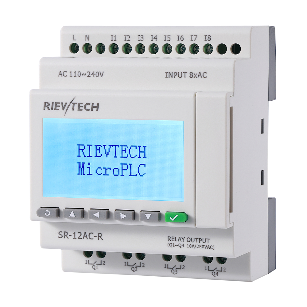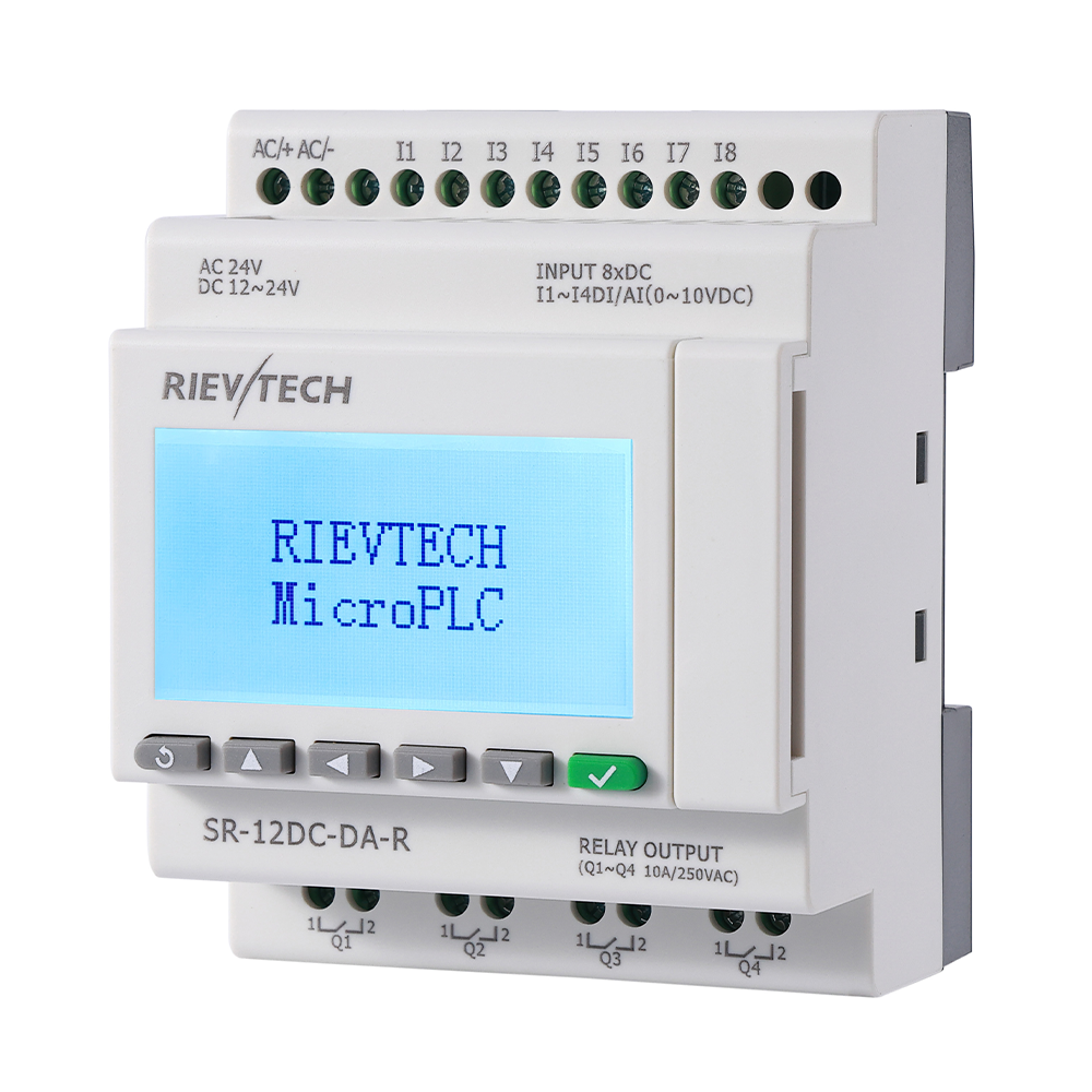
Getting the Ethernet parameters right on an SR-12/22 is a ten-minute job once you know which window does what. The catch is that there are two completely different paths — one through the SR-RS485 channel, one directly over the network — and the PLC behaves differently from the PR series once the link is up. This guide walks through both paths and flags the part that surprises everyone.
What SR12/22 Gives You: Two TCP Connections
SR12/22 supports two TCP connections. The first one, Socket 1, is fixed: SR12/22 always acts as the server there. The second one, Socket 2, can be configured as either a server or a client. That two-socket structure decides how you plan your network — one device connects to the SR as its server, and the SR itself can reach out to a second device as a client.
Defaults and Network Preparation
Default values to remember: the IP address of SR-12/22 is 192.168.0.245, and the server port on Socket 1 is 8008.
Before anything else, set the PC to a fixed IP address in the same subnet as the PLC — for example PC 192.168.0.28, PLC 192.168.0.226. The two can be connected through a switch or router, or directly with a network cable. No DHCP, no "obtain automatically"; a fixed PC address is what makes the rest of this reliable.
Method A: Configure the IP via SR-RS485
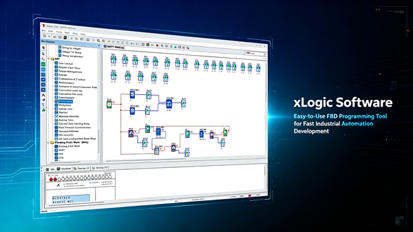
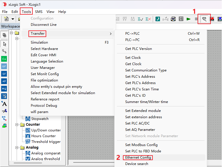
Open the Ethernet parameter configuration window in xLogicSoft — Tools → Transfer → Ethernet Config.
The window is split into three areas.
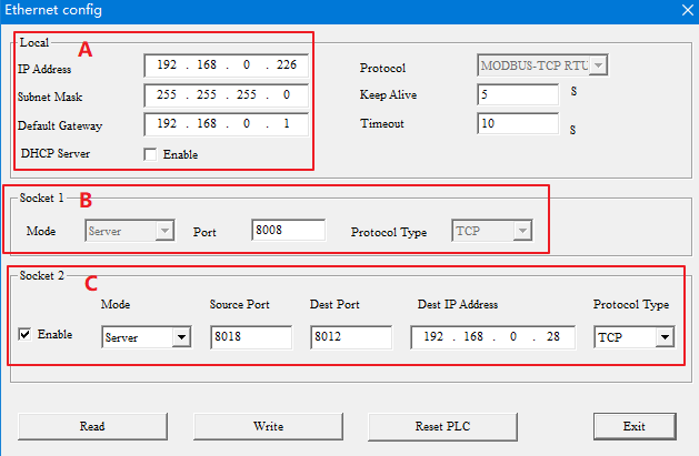
Area A: Local Network Parameters
This is where the PLC's IP address, Subnet Mask and Default Gateway are set. One important trap: if the DHCP Server option is enabled, the values above are ignored and the PLC automatically obtains new IP, mask and gateway settings from the router. Never check this option when you update the firmware — the update fails. Keep Keep Alive and Timeout at their defaults.
Area B: Socket 1
Sets the server port of the first TCP connection (default 8008). Here SR12/22 can only be a server.
Area C: Socket 2
SR12/22 can be set as server or client. Note that the Source Port is used regardless of the mode, so it must never equal the Socket 1 port value.
In Server mode only Source Port matters — its value is the server port.

In Client mode, Source Port, Dest Port and Dest IP Address are all used; Dest Port and Dest IP Address point at the server device you want to reach. Protocol Type defaults to TCP.

Read, Write, Reset

- Read — reads the current Ethernet parameters from the PLC. xLogicSoft usually reads automatically when the window opens; the PC and PLC must be connected normally.
- Write — writes the modified parameters into the PLC. Always click this after editing.
- Reset PLC — restarts the PLC so the new parameters take effect.
- Exit — closes the window and completes the operation.
Method B: Configure Directly over Ethernet
If the PLC is already reachable on the network, you can skip the RS485 cable entirely.
Network Search

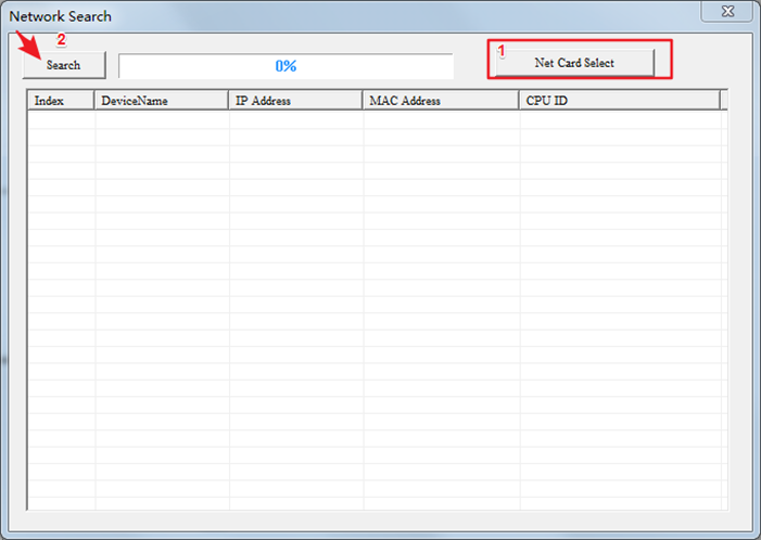
Click the search button in the toolbar to open the Network Search window. First click Net Card Select and pick the PC network card that is connected to the PLC — picking the wrong card means no PLC will ever appear. Then click Search; after a moment the Ethernet PLCs appear in the list with their IP, MAC address and CPU ID.
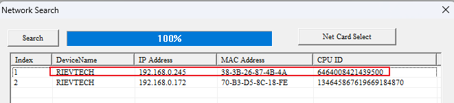
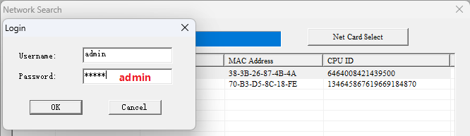
Double-click the target IP and a login screen pops up — the username and password are both admin.
Edit and Apply
After login, the Ethernet config window opens. Click Read first, modify the parameters as in Method A, then click Write. Clicking Close restarts the SR and the new configuration takes effect.
Transferring Programs over Ethernet
The PC running xLogicSoft must be in the same LAN as the SR12/22. The connection settings depend on which side is the server.
When SR12/22 Is the Server
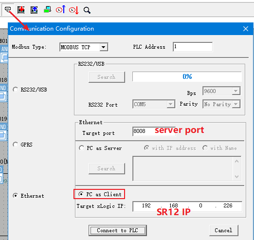
In Communication Configuration, choose MODBUS TCP and Ethernet mode, then set PC as Client. Target port is the server port of the SR (8008) and Target xLogic IP is the PLC's IP address. Click Connect to PLC, and the Download Program (xlogic→PLC) and Upload Program (PLC→xlogic) buttons become available.

When SR12/22 Is the Client
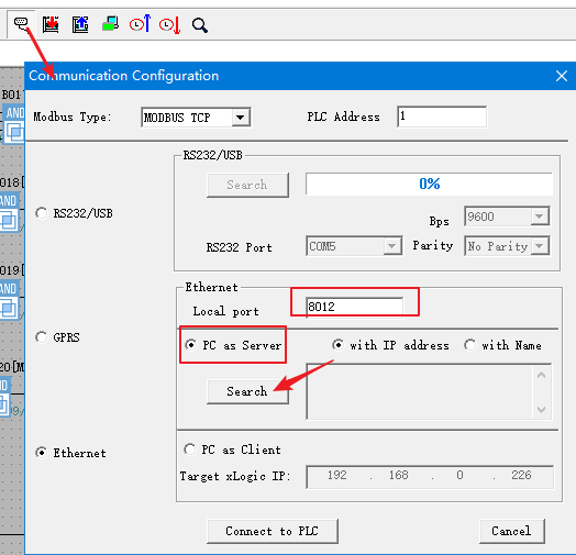
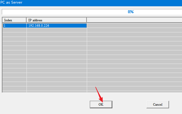
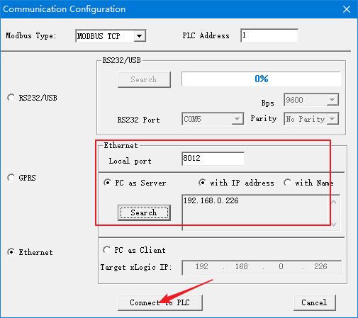
Set PC as Server and give the PC a local port (for example 8012). Click Search, wait for the list, select the PLC IP and click OK, then Connect to PLC. The same Download/Upload buttons appear.

The Part That Surprises Everyone
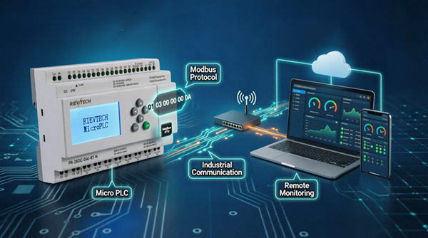
The Ethernet connection of the SR12/22 is a hardware connection, not a software one. Once both sides are configured and physically wired, the PLC hardware connects automatically — and the TCP connection stays alive as long as the physical link exists, whether or not the Modbus block in the program is triggered.
That has a real consequence: with two SR PLCs talking Modbus TCP, the TCP connection between them is occupied even when the client program is not actively exchanging data. A third device or software cannot reuse that connection. This behaviour differs from the PR series Ethernet, so plan your network with it in mind.
LCD Panel and Factory Reset
You can also view and modify the Ethernet parameters from the LCD panel menu on the SR — useful when a laptop is not around. If a configuration gets scrambled and you want a clean slate, restore the Ethernet parameters to the factory state via the same panel menu before reconfiguring.
Working with the PR-N series instead? The PR-N Ethernet setup follows a different, multi-client model — see our guide on configuring the IP address on PR-N series.