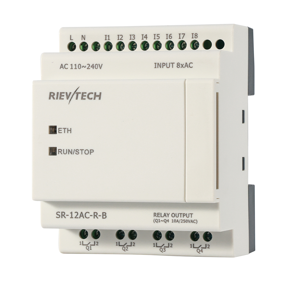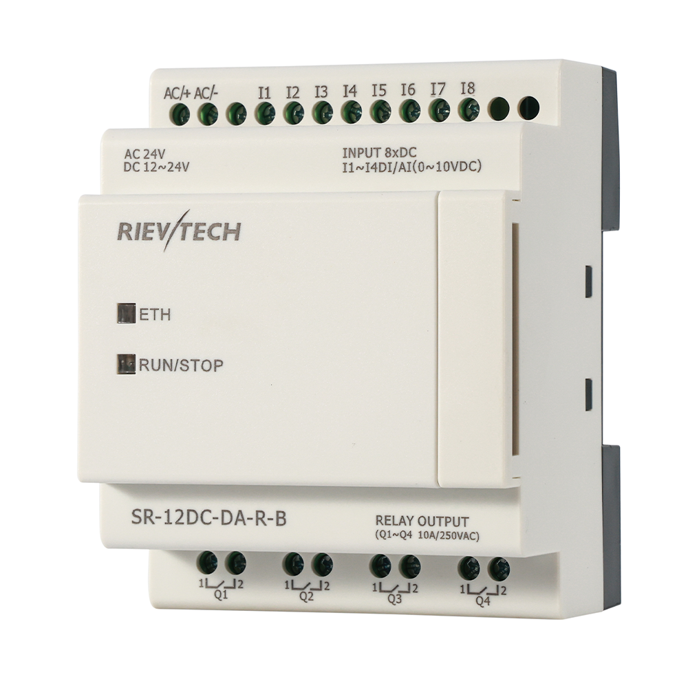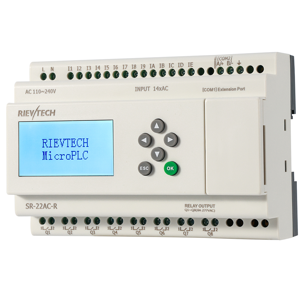
The PR-N series approaches Ethernet differently from the SR series, and the configuration window shows it: one TCP server, one UDP server, up to eight client slots, and a built-in web server. None of it is hard, but the Max Clients rule and the port habits can bite you if you skip them. This guide follows the two official paths — USB cable first, then the cable-free network route — and ends with program transfer over the network.
Method A: Configure the IP via USB Cable
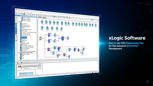
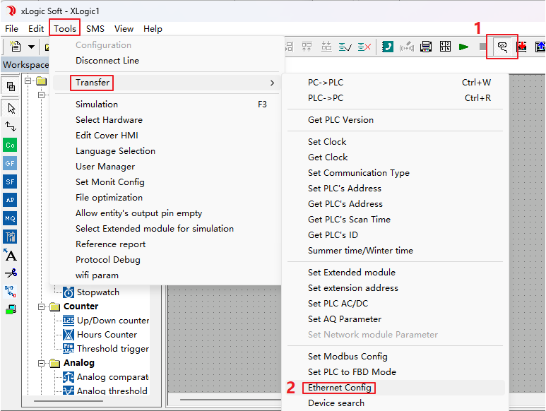
Connect the PLC with the USB cable, then open the Ethernet parameter window in xLogicSoft — Tools → Transfer → Ethernet Config.
The software reads the current configuration automatically, or you can click Read. The window is divided into several areas.
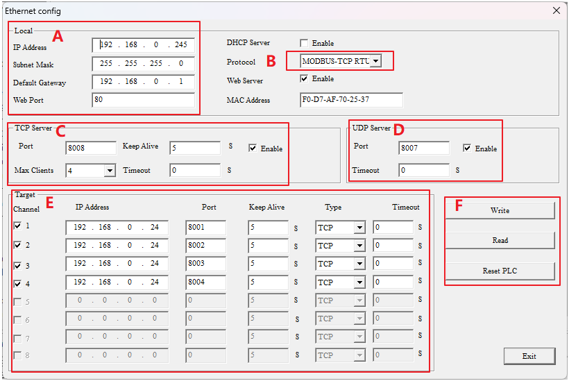
Local Parameters (Area A)
This area sets the IP address, Subnet Mask and Default Gateway of the PLC. The Web Port stays unchanged at 80. If the DHCP Server option is enabled, the PLC obtains its network settings from the router instead of using the values above. Protocol is MODBUS-TCP-RTU by default, the Web Server can be enabled for browser access, and the MAC Address is displayed here for reference.
TCP Server (Area C)
These are the parameters when the PLC acts as a server over TCP:
- Port — the server port of the PLC. Try not to use 8001.
- Keep Alive — connection keep-alive time, default 5 s.
- Max Clients — 0 to 8. When the PLC is a server, this selects how many client channels can connect at the same time, up to 8.
- Timeout — the overtime limit for a connection.
- Enable — checked by default, and it must stay checked when TCP is used.
UDP Server (Area D)
The same idea over UDP: set a port that is different from the TCP port (try not to use 8001 either), a Timeout, and Enable — which must be checked when UDP is used.
Client Targets (Area E)
This table configures the remote servers that the PLC dials into when it acts as a client. Each row holds an IP Address, Port, Keep Alive, Timeout and Type (TCP or UDP, default TCP).
The rule to remember: the number of configured targets plus the Max Clients value in Area C always equals 8. Set Max Clients to 8 and channels 1–8 in Area E become unavailable; set it to 4 and channels 1–4 are available while 5–8 stay locked. Plan the split before you wire anything.
Buttons (Area F)
- Read — reads the network configuration parameters.
- Write — writes the new configuration into the PLC.
- Confirm & Reset — after writing, click this to complete the configuration; the PLC restarts.
Once the parameters are in, test the link before moving on: open CMD.exe on the PC and run ping 192.168.0.245 (use the PLC's address). A reply means the network path is alive.
Method B: Configure the IP without a USB Cable
The PC must have a fixed IP in the same subnet as the PLC — for example PC 192.168.0.28, PLC 192.168.0.223 — connected through a switch, a router, or directly with a network cable.
Network Search

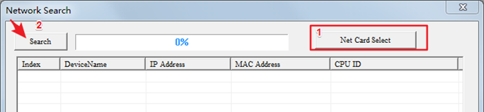
Click the search button in the toolbar to open the Network Search window. The default IP of the PR-N is 192.168.0.245. First click Net Card Select and pick the network card that is actually connected to the PLC — the wrong card means no PLC is ever found. Then click Search and wait; the Ethernet PLCs appear with their IP, MAC address and CPU ID.
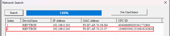
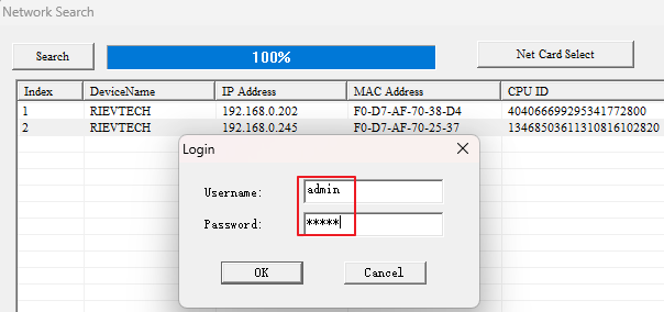
Double-click the target IP, and the login screen appears — the username and password are both admin.
Edit and Apply
After login the Ethernet config window opens. Click Read first, modify the parameters as in Method A, then click Write. A NetSearch prompt may ask you to confirm — click OK. Finally click Close; when asked to restart the PLC, select Yes. The newly configured IP parameters take effect after the restart.
Reading and Writing Programs over the Network
With the network parameters in place, xLogicSoft can transfer programs in two ways.
A) PC as Server
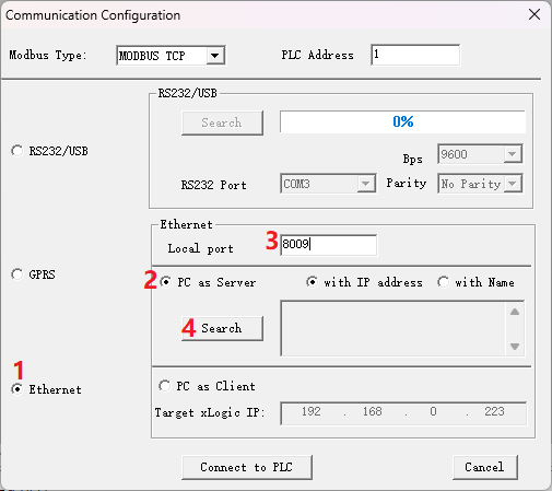
In Communication Configuration, choose MODBUS TCP and the Ethernet mode, then select PC as Server. The Local port here corresponds to the server parameter you set in Area E of the Ethernet config window — for example PC IP 192.168.0.28 with port 8009.
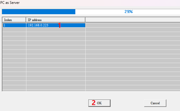
Click Search, wait for the PLC to appear in the list, select its IP address and click OK.
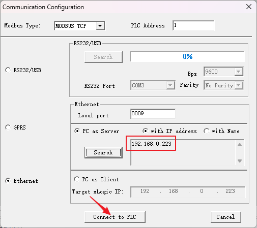
Then click Connect to PLC, and the Download and Upload program buttons become available.

B) PC as Client
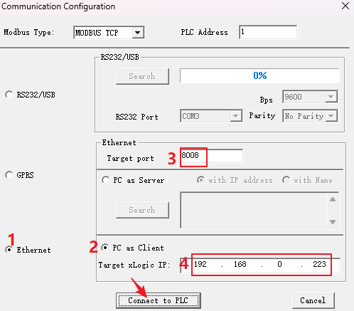
Select PC as Client instead. The Target port is the PLC's TCP server port (8008 in the default configuration — see Area A and Area C of the Ethernet config window), and the Target xLogic IP is the PLC's IP address. Click Connect to PLC, and the same Download/Upload buttons unlock.
One Rule That Saves a Field Visit
Max Clients and the client target table share the same eight slots. If a colleague sets Max Clients to 8 "to be safe", every target row silently disables itself — and the PLC will not dial out to your SCADA until someone sets it back. Keep the two in sync and the sum at eight, and the rest of the PR-N Ethernet setup behaves exactly like the manual says.
Working with the SR series instead? The SR-12/22 has a different, two-socket model — see our guide on configuring the IP address on SR-12/22 series.