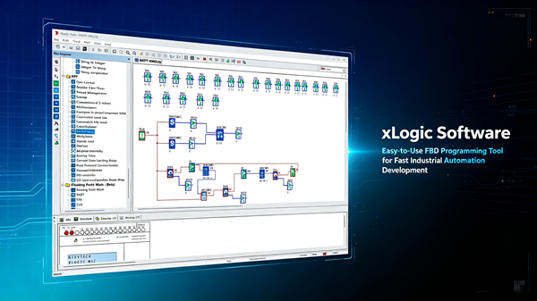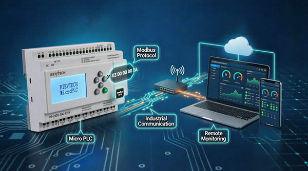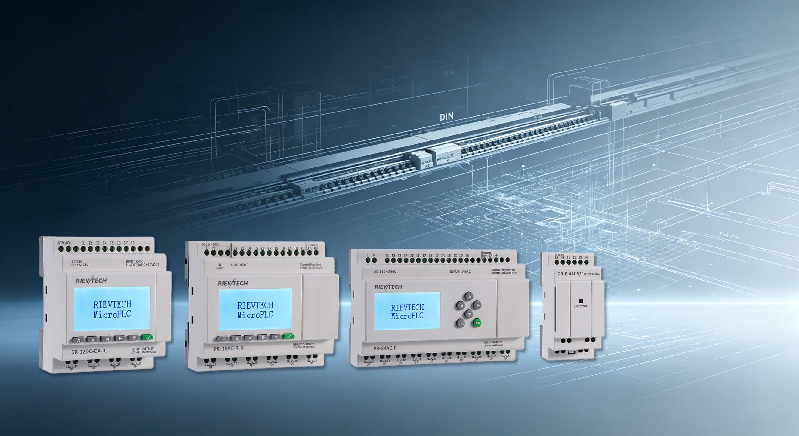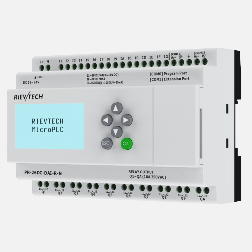
The WIFI-capable Rievtech PLCs — PR-26DC-DAI-RT-WIFI, PR-26DC-DAI-RT-4GWIFI and EXM-12DC-DA-RT-WIFI — put a full TCP channel on the wireless network, which means you can configure the module and transfer programs without touching a cable. The whole flow happens inside xLogicSoft, and it is split into two halves: first you configure the WIFI module itself over a serial connection, then you switch the software to the WIFI link for program transfer. This guide walks through both halves.
Before You Start: Software and Models
You need xLogicSoft V3.3.8.7 or higher. The example models are PR-26DC-DAI-RT-WIFI and EXM-12DC-DA-RT-WIFI, and the configuration steps are the same for both — the only difference is how the serial port is handled, covered below. The current program in xLogicSoft must be the program of the WIFI model you are configuring; otherwise the WIFI parameter window refuses to work.
Step 1: Connect the PLC over the Serial Port
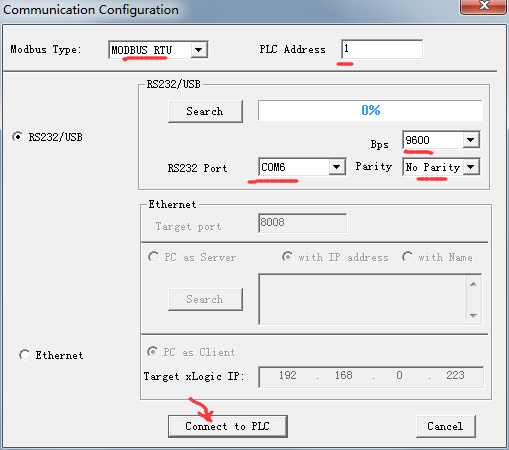
Open the serial port tool in the toolbar, then open the Communication Configuration window and select the COM port of the USB cable, RS232 cable or RS485 converter. Keep the defaults — MODBUS RTU, PLC address 1 — and click Connect to PLC. The serial link is only used to configure the WIFI module; the actual program transfer later goes over the air.
Step 2: Open the Right Program Model
Create or open a PR-26DC-DAI-RT-WIFI program. If you are configuring an EXM-12DC-DA-RT-WIFI, create or open an EXM-12DC-DA-RT-WIFI program instead. The model shown at the bottom of the xLogicSoft window must match the hardware.


Step 3: Open the WIFI Configuration Window
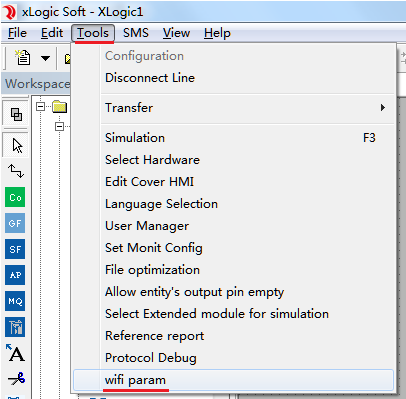
Select the menu Tools → wifi param.
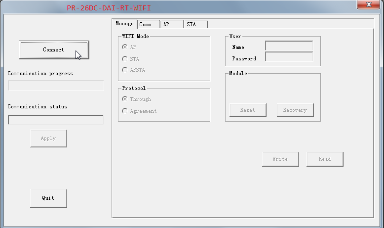
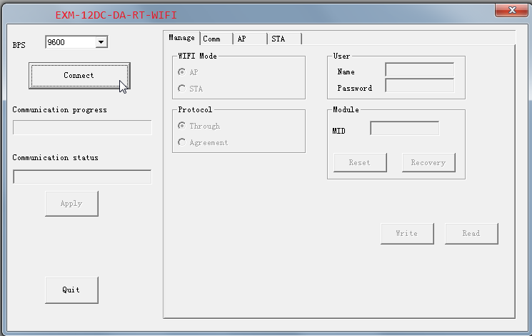
The configuration window has four pages: Manage, Comm, AP and STA, with Connect, Apply and Quit buttons on the left. One difference between the two models shows up right away: PR-26DC-DAI-RT-WIFI does not need a baud rate selection — the software picks it automatically. While EXM-12DC-DA-RT-WIFI asks you to choose it, the default is 9600; if the WIFI module was restored to factory settings, select 57600.
Step 4: Configure the Four Pages
Click Connect. A prompt warns that the PLC must be STOPPED before setting WIFI parameters — confirm it. The progress bar runs and may pause; that is normal. If it stalls for too long or the connection fails, power off and restart the PLC, then connect again. When the bar reaches 100% you see "Connect end!".
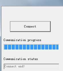
On every page the sequence is the same: click Read first to load the current parameters, modify, then click Write. Click Apply only after you have finished all pages — that is what makes the changes take effect.

Manage: WIFI Mode, Protocol, User and Module
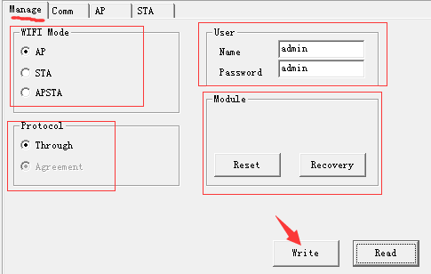
- WIFI Mode — AP: the PLC creates its own WIFI network that phones and laptops can join. STA: the PLC joins an existing WIFI network as a terminal. APSTA: both at once.
- Protocol — keep the default Through.
- User — not used on PR-26DC-DAI-RT-WIFI. On EXM-12DC-DA-RT-WIFI this login (Name and Password, both admin by default) is required when you configure the module through a browser.
- Module — Reset restarts the WIFI module without restarting the PLC; Recovery restores the module to factory settings (wait for the progress bar, confirm OK, then power off and restart the PLC).
Comm: Network Mode, Port and Server
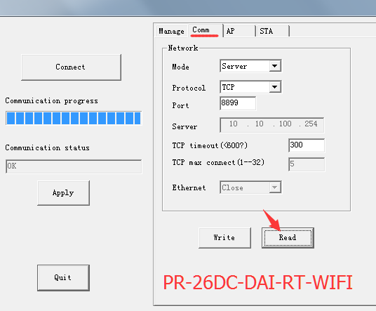
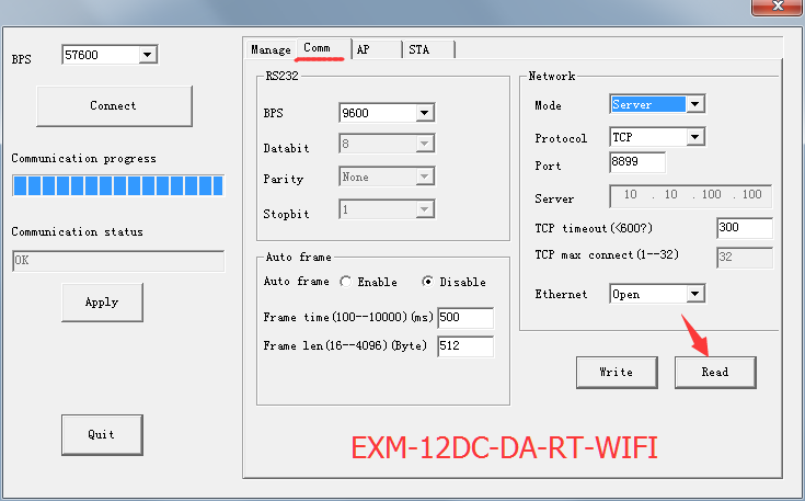
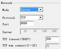
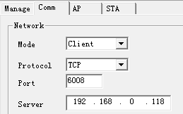
In the Network section, set Mode to Server or Client. Protocol stays TCP, Port is 8899 by default. In Server mode the PLC listens on that port; in Client mode the PLC dials out to the Server address you enter, also on port 8899. TCP timeout is 300 and TCP max connect accepts 1 to 32. One important note: although the maximum number of TCP connections is 32, when Modbus read/write is performed the PLC can only communicate with one network device at a time.
AP: Access Point Settings
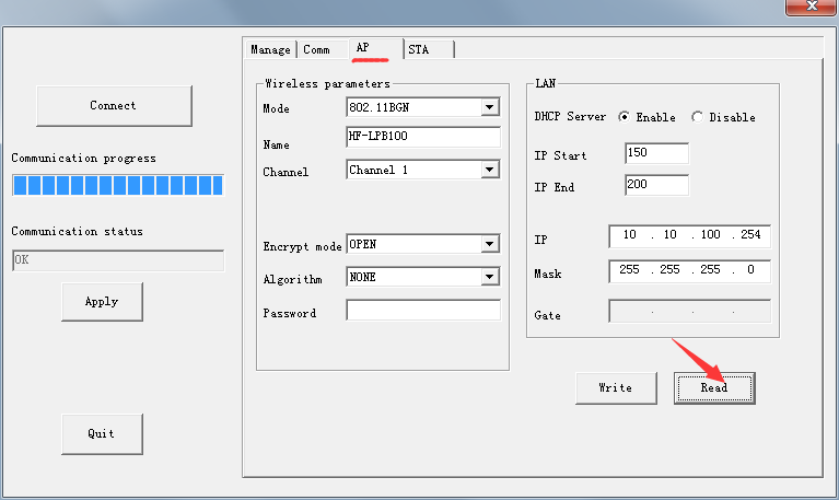
This page sets the WIFI network the PLC broadcasts. Configure Mode (802.11BGN), Name, Channel, Encrypt mode, Algorithm and Password. In the LAN section, the IP 10.10.100.254 is the PLC's own address in AP mode and also the gateway for devices joining this WIFI. It is recommended to enable the DHCP Server option. If you set WIFI Mode to STA, this page does not need to be modified.
STA: Joining an Existing WIFI
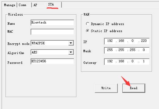
This page sets the WIFI network the PLC connects to: the network Name, MAC, Encrypt mode, Algorithm and Password in the Wireless section, plus a WAN mode — Dynamic or Static IP — with IP, Mask and Gateway. Use a static IP in the same subnet as the rest of the installation for predictable addressing. If you set WIFI Mode to AP, this page does not need to be modified.
Apply and Restart
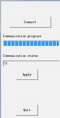
After all pages are written, click Apply on the left. It is recommended to power off and restart the PLC once the WIFI parameters are configured, so the module starts clean with the new settings.
Step 5: Read and Write the Program over WIFI
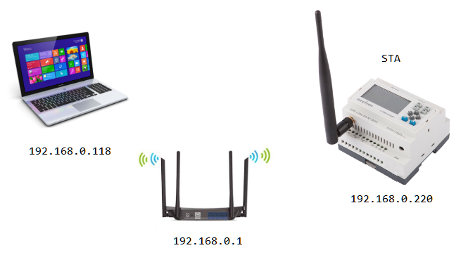
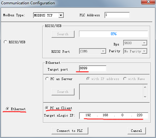
For this part the PLC's WIFI works in STA mode, and the PLC's WIFI and the PC's IP must be on the same LAN — for example PC 192.168.0.118, router 192.168.0.1, PLC 192.168.0.220.
When the PLC Is the Server

Open the serial port configuration window.

In xLogicSoft open the Communication Configuration window, choose MODBUS TCP and the Ethernet mode, then set PC as Client. Target port is the PLC's server port (8899) and Target xLogic IP is the PLC's IP address.
Click Connect to PLC, and the Download and Upload program buttons become available.

When the PLC Is the Client

Open the serial port configuration window.
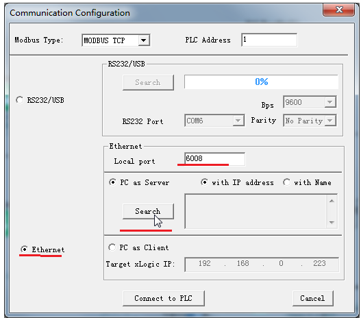
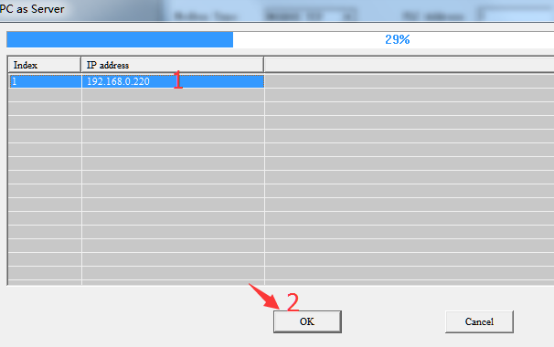
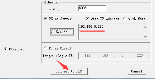
Select PC as Server instead, and give the PC a local port — for example 6008. Click Search, wait for the PLC to appear in the list, select its IP address and click OK, then Connect to PLC. The same Download/Upload buttons unlock once the link is up.
Two PLCs exchanging data over WIFI? See our guide on Modbus communication between 2 WiFi PLCs, and for a three-node network with one PLC as access point, see Modbus communication between 3 WiFi PLCs.