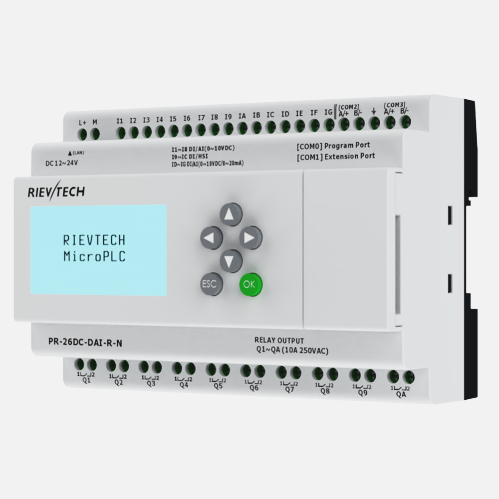
Three WIFI PLCs can form a complete Modbus network with no router at all: one PLC broadcasts its own WIFI as an access point, and the other two join it as stations. In the example below three PR-26DC-DAI-RT-WIFI share one network, the AP node doubles as the Modbus server, and the two clients exchange data through it. The WIFI parameter procedure is the same as in our WiFi PLC program transfer guide; here the focus is on the role split and the sample program that chains values across all three nodes.
The IP Plan
One PLC provides the network, so it owns the AP addresses. The other two take static addresses inside it.
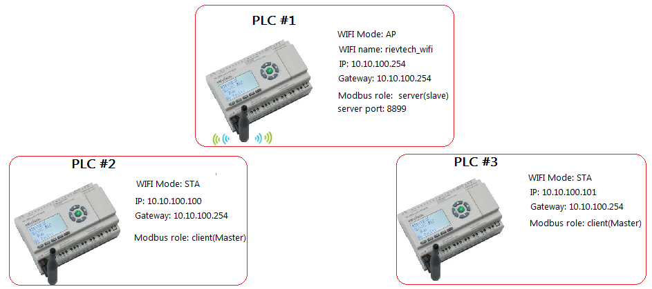
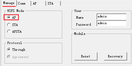
- PLC #1 — WIFI Mode AP, WIFI name rievtech_wifi, IP 10.10.100.254, Gateway 10.10.100.254, Modbus role server (slave), server port 8899.
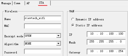
- PLC #2 — WIFI Mode STA, IP 10.10.100.100, Gateway 10.10.100.254, Modbus role client (master).
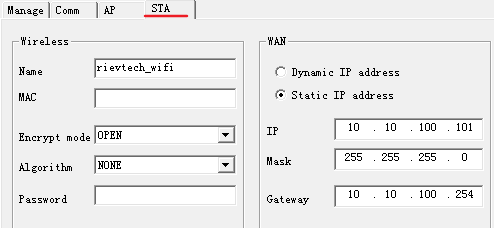
- PLC #3 — WIFI Mode STA, IP 10.10.100.101, Gateway 10.10.100.254, Modbus role client (master).
Note that the PLC #1 address is also the gateway for the other two — in AP mode the PLC acts as both the access point and the router for the network it creates.
Configure the Three PLCs
For each PLC, open its PR-26DC-DAI-RT-WIFI program, connect the serial cable, open Tools → wifi param and click Connect (confirm the stop prompt). Then set the pages.
PLC #1 (Access Point + Server)
- Manage — WIFI Mode: AP; the rest unchanged.
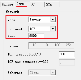
- Comm — Mode: Server, Protocol: TCP, Port: 8899, TCP max connect 5.
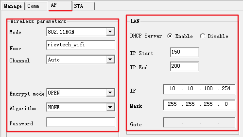
- AP — Mode 802.11BGN, Name rievtech_wifi, Channel Auto, Encrypt mode OPEN, Algorithm NONE. In the LAN section: DHCP Server Enable, IP 10.10.100.254, Mask 255.255.255.0, Gate 10.10.100.254.
PLC #2 and PLC #3 (Stations + Clients)
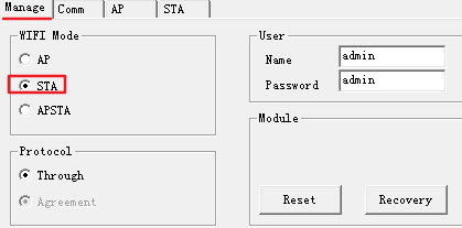
- Manage — WIFI Mode: STA.
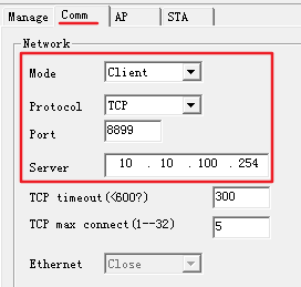
- Comm — Mode: Client, Protocol: TCP, Port: 8899, Server: 10.10.100.254 (the AP PLC's address).
- STA — join rievtech_wifi (Encrypt mode OPEN, Algorithm NONE). WAN: Static IP — 10.10.100.100 for PLC #2, 10.10.100.101 for PLC #3 — Mask 255.255.255.0, Gateway 10.10.100.254.
Write every page, click Apply, then power off all three PLCs and restart them — PLC #1 first, so the network is up before the stations try to join.
Sample Program: Relay a Counter Value across the Network
The requirement: PLC #3 wants to read the value of counter B003 in the PLC #2 program. Because PLC #2 and PLC #3 are both clients of the same server, the value travels in two hops through PLC #1.
- PLC #2 — the counter B003 runs normally. A rising-edge block (PK7[ED] into B001) triggers a write block (B004) that pushes the value of B003 into AF1 of PLC #1.
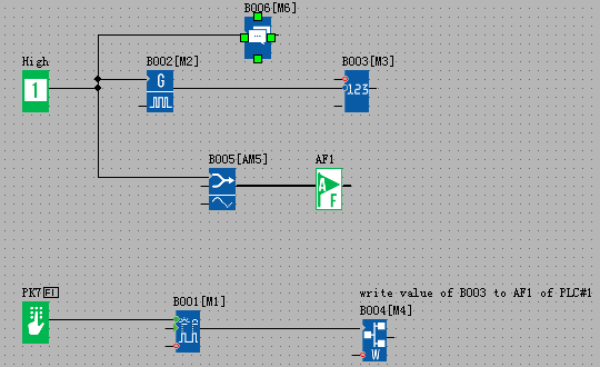
- PLC #1 — receives that value into its AF1 and holds it. PLC #1 is the Modbus server, so both clients can reach this AF1.
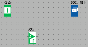
- PLC #3 — a read block reads AF1 of PLC #1 and saves it to its own AF1. The initial value of that data is B003 of PLC #2, so the counter value has now crossed the whole network.
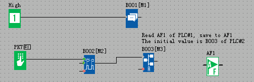
In practice, PLC #2 writes to the server and PLC #3 reads from the server, and the server PLC simply hosts the register in between. Test the chain with the three sample programs running and the monitor window open on each node.
The Single-Channel Rule
Every WiFi PLC's wireless function is implemented by a wifi-to-serial module, and that module's serial port communicates with the PLC's CPU chip. The consequence: each PLC's WIFI can carry only one channel of communication at a time. In Modbus communication, if a Modbus block occupies this channel, any other Modbus block using the WIFI channel must not be triggered at the same moment — doing so causes communication failure, slowness or data errors. If you need multiple Modbus blocks that use the WIFI channel, trigger them in turn, one after another, and keep the exchange window short.
This is the same single-channel behaviour you see with two PLCs — see our 2 WIFI PLCs Modbus guide for the two-node version.