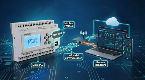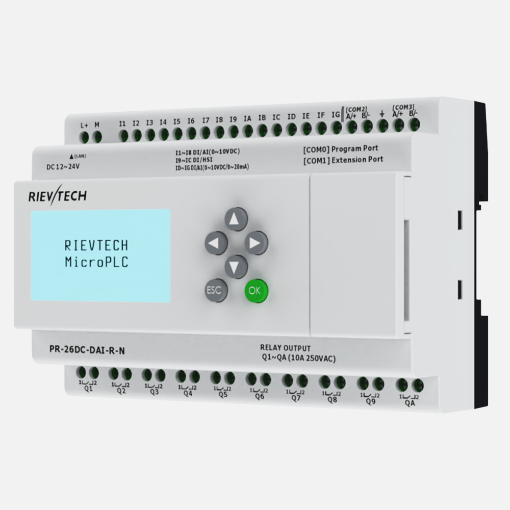
Two WIFI PLCs can talk Modbus over the air with nothing but a wireless router between them. The setup uses two PR-26DC-DAI-RT-WIFI as the example: both join the same router as STA stations, one acts as the Modbus server (slave) and the other as the client (master), and the client reads a value from the server's program. The WIFI parameter procedure itself is the same as in our WiFi PLC program transfer guide; this article focuses on the roles, the exact values and a working sample program.
The Two Roles
The network in this example is simple: one wireless router provides the WIFI, and two PLCs connect to it.
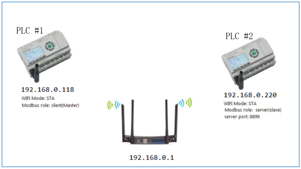
- PLC #1 — IP 192.168.0.118, WIFI Mode STA, Modbus role client (Master). It reads data from PLC #2.
- PLC #2 — IP 192.168.0.220, WIFI Mode STA, Modbus role server (Slave), server port 8899. It answers the client's requests.
The client is the one that initiates; the server only responds. Assign the addresses before wiring anything into the program.
Configure the WIFI Parameters
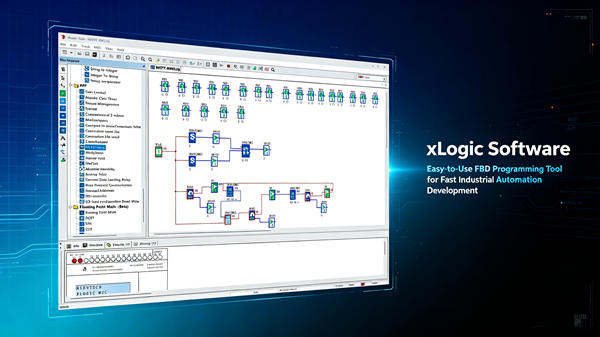
For each PLC, open the matching PR-26DC-DAI-RT-WIFI program in xLogicSoft, connect the USB or RS232 cable, open Tools → wifi param and click Connect (confirm the "PLC must be STOPPED" prompt). Then set the pages as follows.
PLC #1 (Client)
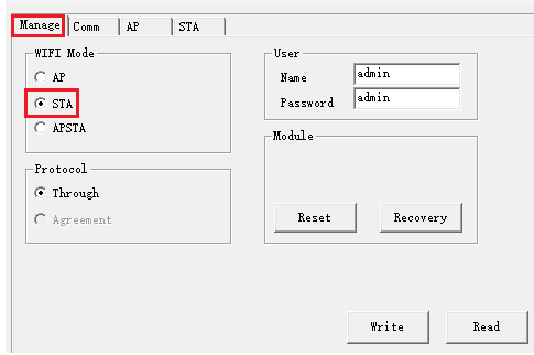
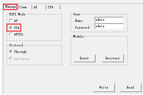
- Manage — select STA; the rest stays unchanged.
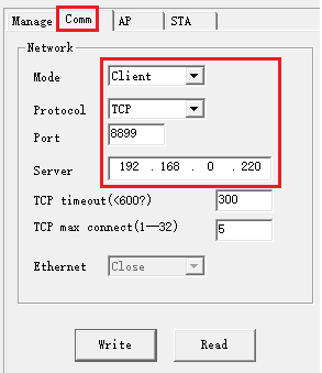
- Comm — Mode: Client, Protocol: TCP, Port: 8899, Server: 192.168.0.220 (the IP of PLC #2), TCP max connect 5.
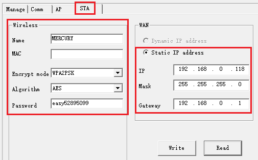
- STA — join the router's WIFI: for example Name MERCURY, Encrypt mode WPA2PSK, Algorithm AES, Password easy52895099, Static IP 192.168.0.118, Mask 255.255.255.0, Gateway 192.168.0.1.
PLC #2 (Server)
- Manage — select STA.
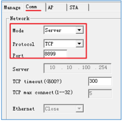
- Comm — Mode: Server, Protocol: TCP, Port: 8899, TCP max connect 5.
- STA — the same WIFI network as PLC #1, with its own Static IP 192.168.0.220, Mask 255.255.255.0, Gateway 192.168.0.1.
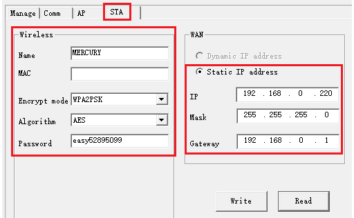
After writing each page, click Apply once everything is set, then power off and restart both PLCs.
Sample Program: Read a Value from the Server PLC
Say PLC #1 needs the value of AF1 from PLC #2. In the PLC #1 program, place a Modbus Read block and set it as follows:
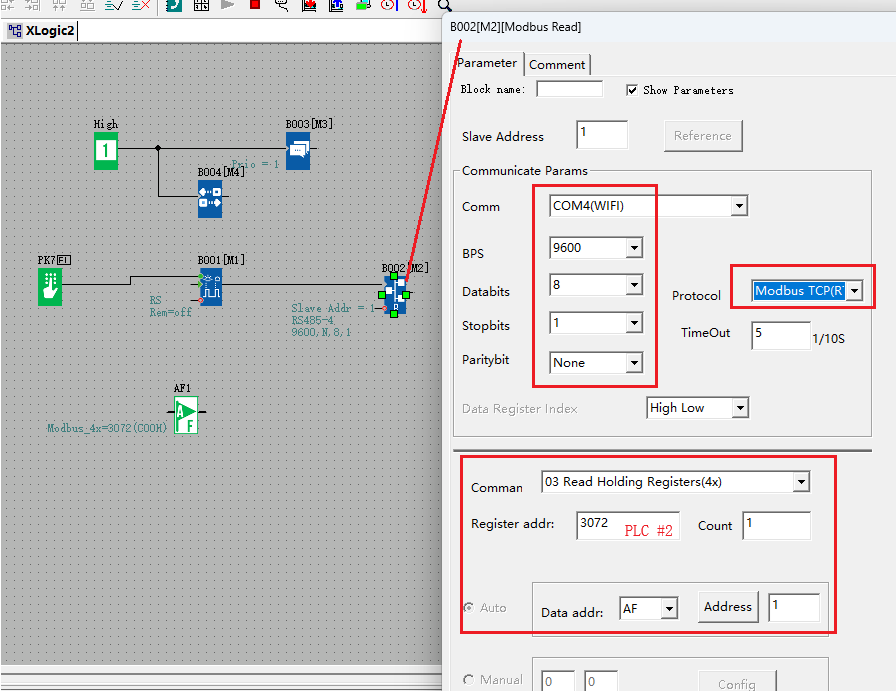
- Slave Address — 1 (the address of PLC #2).
- Comm — COM4 (WIFI), BPS 9600, 8 data bits, 1 stop bit, no parity.
- Protocol — Modbus TCP (R).
- Command — 03 Read Holding Registers (4x).
- Register addr — 3072, which maps to the AF registers of PLC #2.
- Count — 1.
- Data addr — AF, address 1: the value lands in PLC #1's own AF1.
Trigger the block periodically — the usual approach is a time base or a pulse flag — and the local AF1 tracks the remote value over the WIFI link.
One Rule to Respect
The WIFI module of each PLC is a wifi-to-serial bridge: the module's serial port talks to the PLC's CPU, and one PLC's WIFI can carry only one channel of communication at a time. During a Modbus exchange, a block that occupies the WIFI channel blocks other Modbus blocks that use the same channel — firing them together causes communication failure, slowdowns or data errors. If a program needs several Modbus blocks over WIFI, trigger them one at a time in sequence. This is exactly the behaviour described for three-node networks in our 3 WIFI PLCs guide.