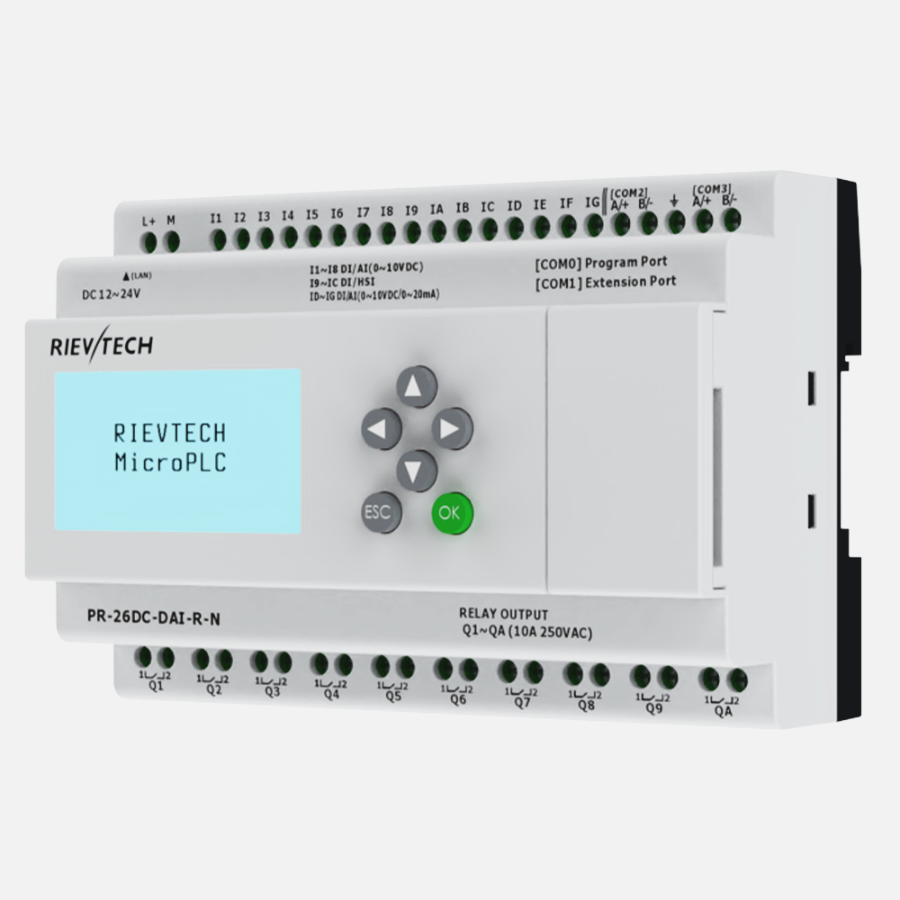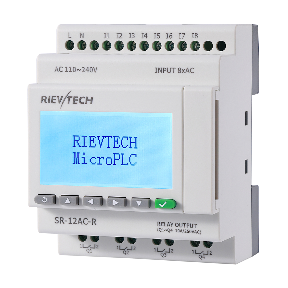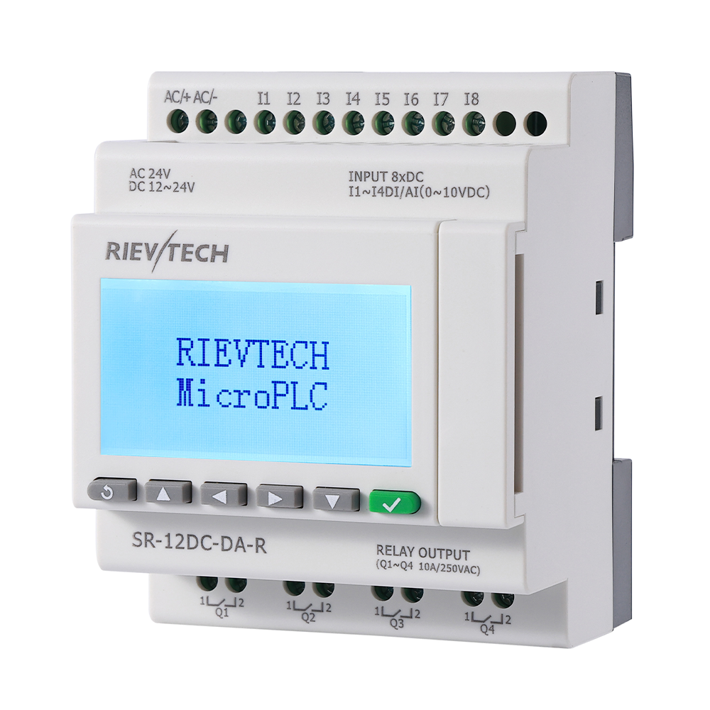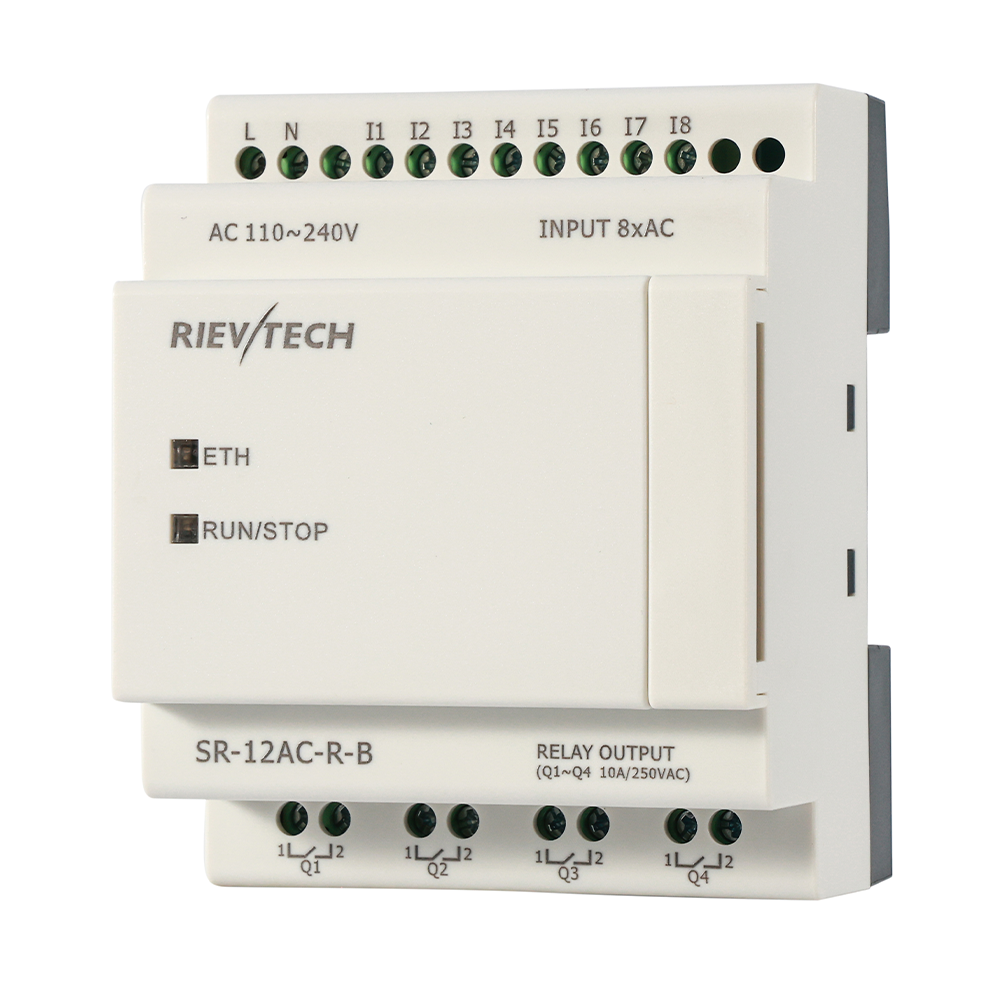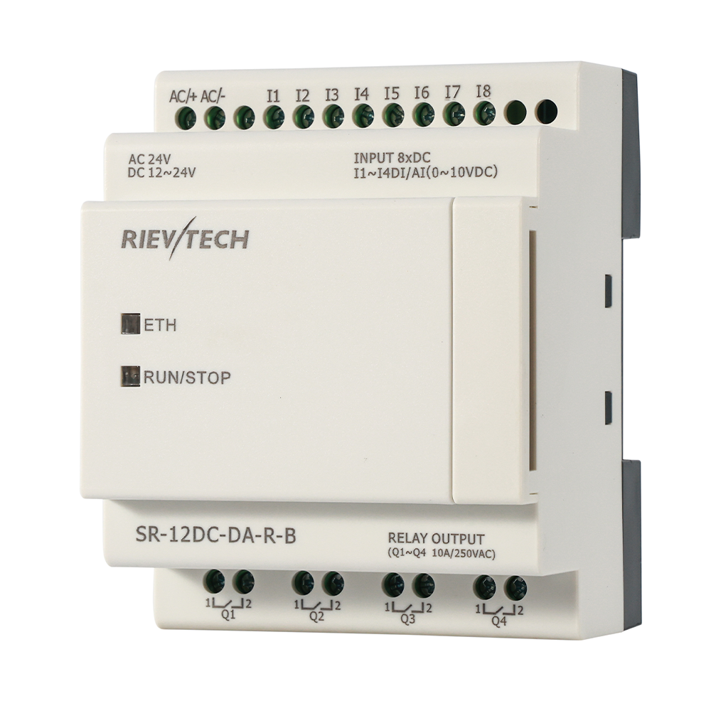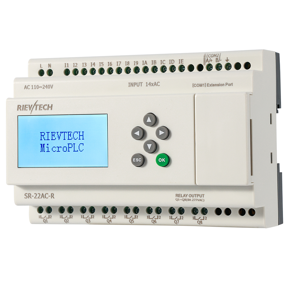
Getting an HMI talking to an Ethernet PLC is mostly an addressing exercise: three devices, one subnet, two configuration windows and one protocol setting. The example below uses the RTS007 HMI and a Rievtech Ethernet PLC, and it covers the HMI side, the PLC side and the connection in Rievtech Studio — the pieces you need in the right order the first time.
1. Put HMI, PLC and PC on the Same Subnet
All three devices must be in the same local area network. A clean example: HMI 192.168.0.200, PLC 192.168.0.100, PC 192.168.0.101, all with mask 255.255.255.0. If the PC is not on the same subnet you can still edit projects offline, but the download and the live link will fail, so settle the addressing before touching the cable.
2. Change the HMI IP Address
The default IP of the HMI is 192.168.0.200. There are two ways to change it.
Method A: Rievtech Studio
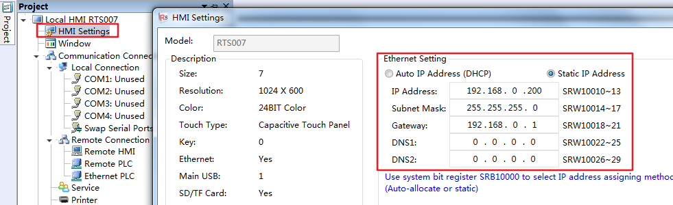
In Rievtech Studio, open HMI Settings under the project tree and go to the Ethernet Setting section. Choose Auto IP Address (DHCP) or Static IP Address, then fill in IP Address, Subnet Mask, Gateway and DNS1/DNS2. The window shows the register mapping behind each field — IP uses SRW10010~13, Subnet Mask SRW10014~17, Gateway SRW10018~21, DNS1 SRW10022~25, DNS2 SRW10026~29 — and the system bit register SRB10000 selects the assignment method (auto or static). Download the project to the HMI and the HMI starts using the new IP.
Method B: Directly on the HMI Panel
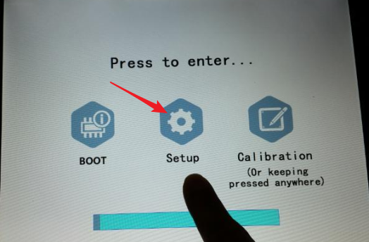
At power-on, press and hold any point on the touch screen without releasing to enter the special mode. Three options appear: BOOT, Setup and Calibration. Enter Setup, select Network, and modify the HMI's IP there — Static IP or DHCP — then enter Advanced and restart the HMI. No PC and no project download needed for this path.
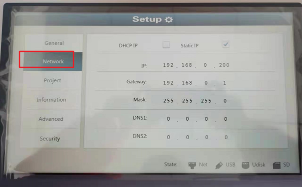
3. Set the IP Parameters of the PLC
On the PLC side, open the Web Server config window (Tools → Transfer → Ethernet Config in xLogicSoft, or the equivalent panel path) and set the PLC's Local parameters: IP Address, Subnet Mask and Default Gateway. The TCP Server section listens on port 8008 by default with Max Clients 4, and the UDP Server uses port 8007. Write the parameters and confirm the reset so they take effect. For the full walkthrough of every field — DHCP behaviour, TCP/UDP ports and the client target table — see our PR-N series Ethernet setup guide.
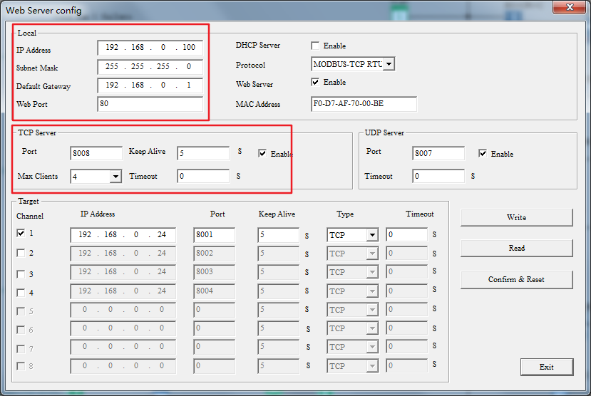
4. Add the Network PLC in Rievtech Studio
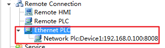
In Rievtech Studio, open Communication Connection in the project tree, select the Ethernet PLC tab, and click Add.
In the "Ethernet PLC" configuration window, set the following:
- Manufacturer — RIEVTECH.
- Device Type — RIEVTECH FBD_ETH.
- Device Alias — cannot be empty; the default is Device1.
- Default Station No. — Constant 1 (a Synchronize Station No. option is available if you want the station number to follow another value).
- Communication Setting — the IP address of the Ethernet PLC, fixed at 192.168.0.100 in this example, and Port No. 8008 — the same port the PLC's TCP server listens on.
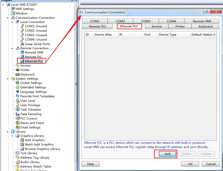
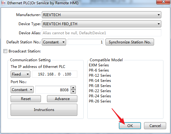
The Compatible Model list shows which series work here: EXM Series and PR-6, PR-12, PR-14, PR-18, PR-22, PR-24 and PR-26 series. Click OK to save, and the connection appears in the list as Network PLC: Device1:192.168.0.100:8008.
5. Use the Connection in a Project
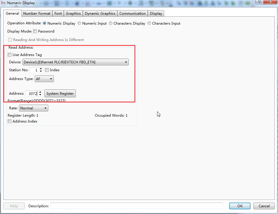
With the Ethernet PLC added, any address in the project can point at it. For a numeric display or input, set the device to Device1 [Ethernet PLC:RIEVTECH FBD_ETH], Station No 1, and choose the address type — for example AF with address 3072, which falls in the DDDD range 3072 to 3327 for system registers, Register Length 1. The HMI then reads and writes that register directly over the network through port 8008.
Once the download completes, power-cycle the HMI and confirm the IP from its Network screen; then watch the register value live in Rievtech Studio's monitoring window. A stable value on both sides means the HMI-to-PLC path is fully wired — in software, not just in copper.