A trainee once asked why his filling machine program sometimes skipped a step and filled the bottle before the bottle was positioned. The anwser was not a missing timer — it was missing state. His program was a pile of independent conditions; real sequential machines are a state machine, and the difference is the difference between a program that works on paper and a program that works on Monday.
Sequential control is everywhere in automation: a filling line, a turntable, a stamping press, a paint booth. The classic mistake is writing each output as a loose condition — "when sensor A and timer B, open valve C" — and then debugging the impossible combinations at 2 AM. The fix is to stop thinking in outputs and start thinking in states.
What a State Machine Actually Is
A state machine is a set of named steps and the rules for moving between them. The machine is always in exactly one step: WAIT, POSITION, FILL, SEAL, EJECT. Each step has entry actions, exit conditions, and guards. The bottle is filled only in the FILL step, and the FILL step is only reachable from POSITION when the bottle sensor confirms position. It sounds like bureaucracy; it behaves like engineering.
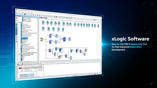
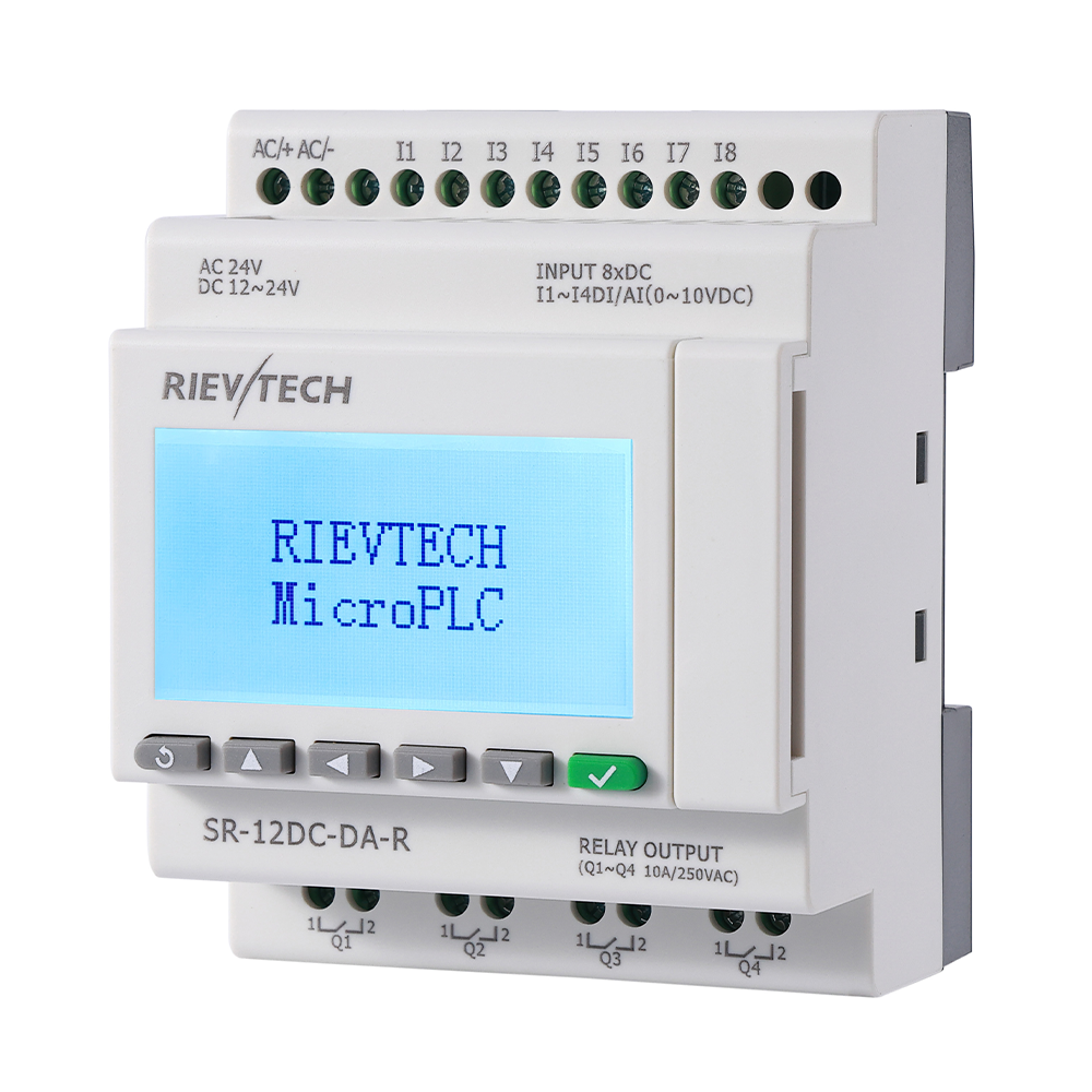
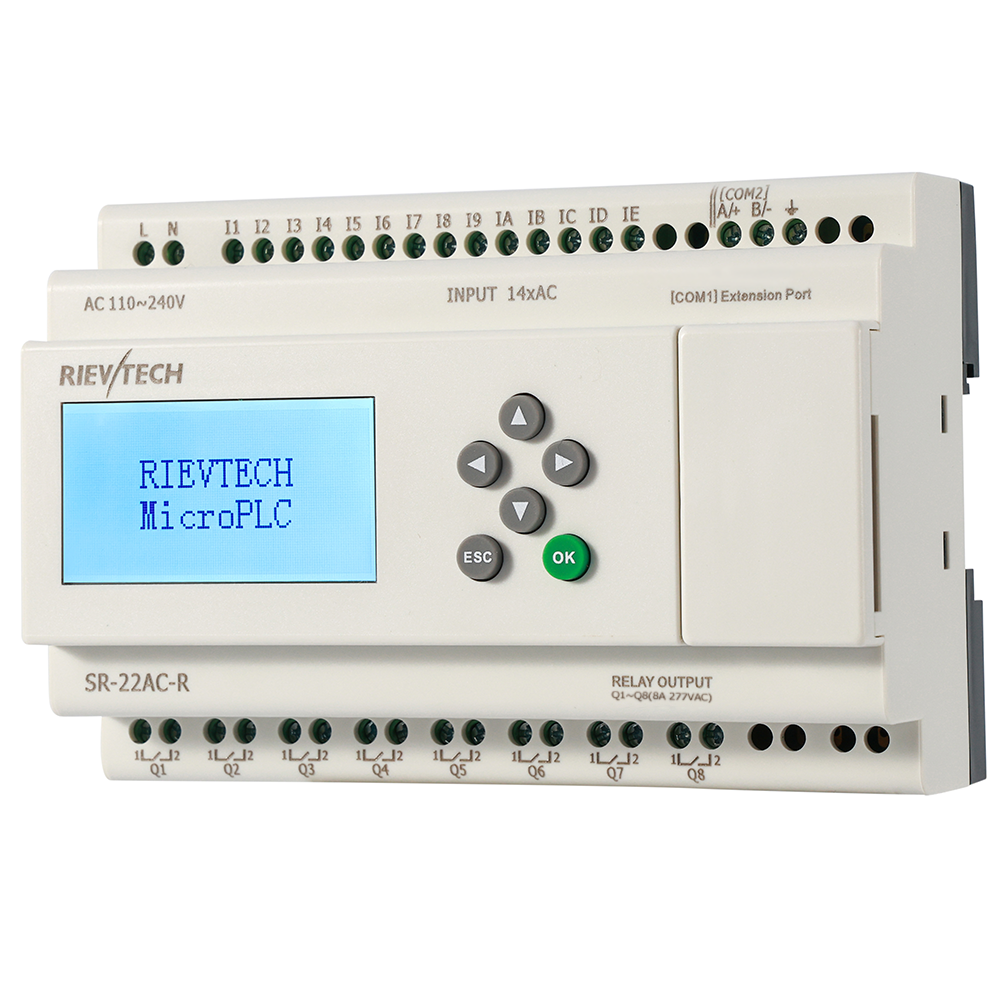
In xLogicSoft's FBD, a state machine maps cleanly onto the classic Shift Register pattern or onto F flags used as step bits. The pattern: one F flag per step, a set of transition conditions, and a one-shot transition block so the machine advances exactly one step per event. Because the current step is always visible — the LCD shows which F flag is active — the operator and the maintenance man can see at a glance where the machine thinks it is. That single feature cuts troubleshooting time more than any diagnostic manual.
Building It: Three Filling Stations
Take a simple three-station example: a bottle arrives, is filled, is capped. The steps:
- Step 0 IDLE: all outputs off. Transition: bottle-present sensor, start pushbutton.
- Step 1 POSITION: conveyor runs until the bottle stops at the filling head. Transition: position sensor.
- Step 2 FILL: fill valve opens for a timed duration or until the level sensor trips. Transition: timer done.
- Step 3 CAPPING: capper lowers and presses. Transition: pressure-confirmed, timer done.
- Step 4 EJECT: conveyor runs to move the bottle out. Transition: exit sensor clears.
Each transition uses an On-Delay or a Wiping Relay (one-shot) block so the advance happens exactly once. The guard on every transition is the step itself — Step 2 cannot start unless the machine is in Step 1, period. The bottle cannot be filled early because "early" does not exist as a condition; it is not in the step table, and the bottle is not positioned untill the machine has left POSITION.
Give the operator a manual step mode before you give them anything else. A selector input lets the machine advance one step at a time through the sequence, so a setup technician can jog the line through POSITION, FILL and CAPPING individually while watching the actuators. The state machine makes this trivial — advancing one step is just forcing the next transition — and it turns commissioning from a mystery into a checklist. Machines that cannot be stepped through manually are machines that get debugged with a screwdriver.
The Failure Mode Test
Here is the exercise that reveals whether you have built a state machine or a condition pile: list the emergencies. Bottle jammed under the fill head? The machine should stay in FILL, stop the pump, and alarm — not wander into EJECT and dump product on the floor. Sensor fails and reports "bottle present" forever? The machine should time out the POSITION step and alarm, not fill the same invisible bottle all night. Sensor fails the other way, "never present"? The machine waits patiently — that is fine, that is what machines should do.
Write a watchdog into the program: if the machine sits in any non-IDLE step for longer than the step's maximum time, drop to a FAULT state, cut the outputs, and flash the alarm. The maximum time is a number you already know from the cycle time — you are not guessing, you are enforcing physics.
Decide what happens after a fault before the fault happens. The common choice: the machine stops where it is, the operator clears the cause, presses reset, and the sequence returns to IDLE — or to the start of the interrupted step if the product is still safe. Returning to IDLE is simpler and safer for small machines; resuming mid-cycle is faster but demands that every output state is known and proven. For a filling machine, IDLE is the honest answer — a half-filled bottle is scrap either way.
Why FBD Beats Ladder for This
One debugging habit pays for itself immediately: make the current step visible on the front LCD as a plain number. The operator's first report becomes "it is stuck on step 4," not "it does something weird," and step 4 points straight at its transition condition. In xLogicSoft the flag bits are right there in the monitor window, so a laptop session shows the same picture the LCD shows. Matching the operator's words to the program's state cuts a two-hour hunt down to twenty minutes every single time.
Ladder logic can express a state machine, but it takes a hundred rungs and a diagram nobody reads. In FBD, the step structure sits in front of you: the Shift Register or the flag block shows the current step, the transition blocks are visible, and the sequence reads top to bottom. The xLogicSoft environment includes around seventy function blocks, and a five-step machine with interlocks fits comfortably in one program page. When the machine changes — new station, new sensor — you add a step and two transitions instead of rewiring the logic.
Start with the step table on paper, then the flags, then the transitions. The program will be boringly correct, and boringly correct is the highest compliment an automation program can earn. Machines do not need clever; they need predictable.