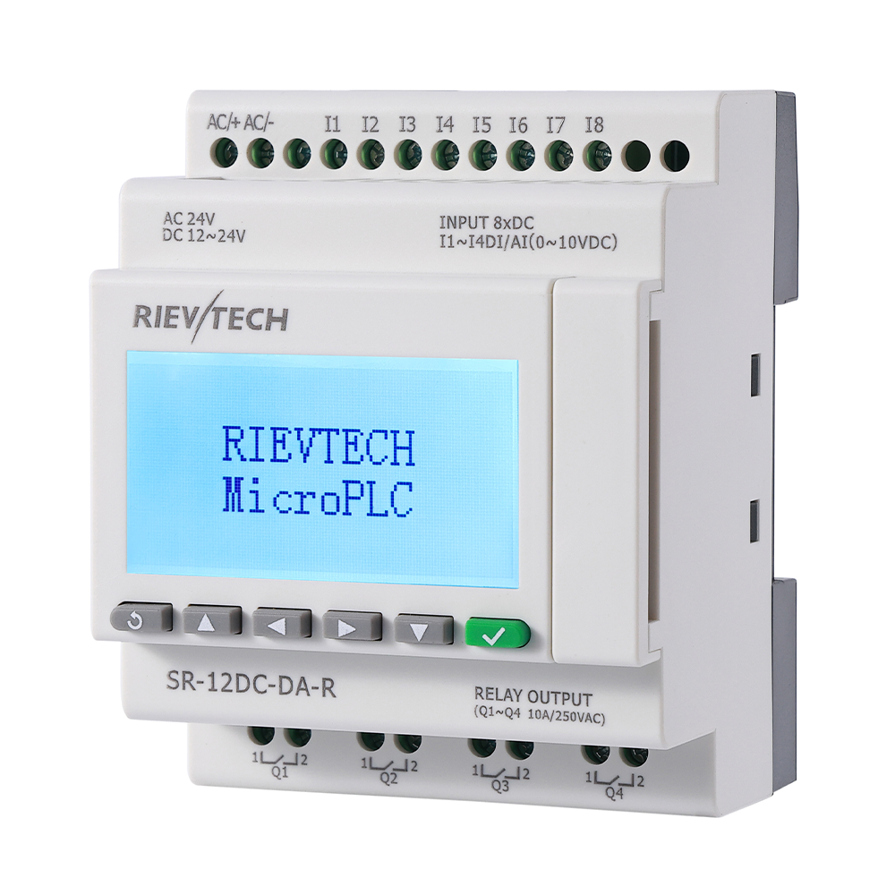
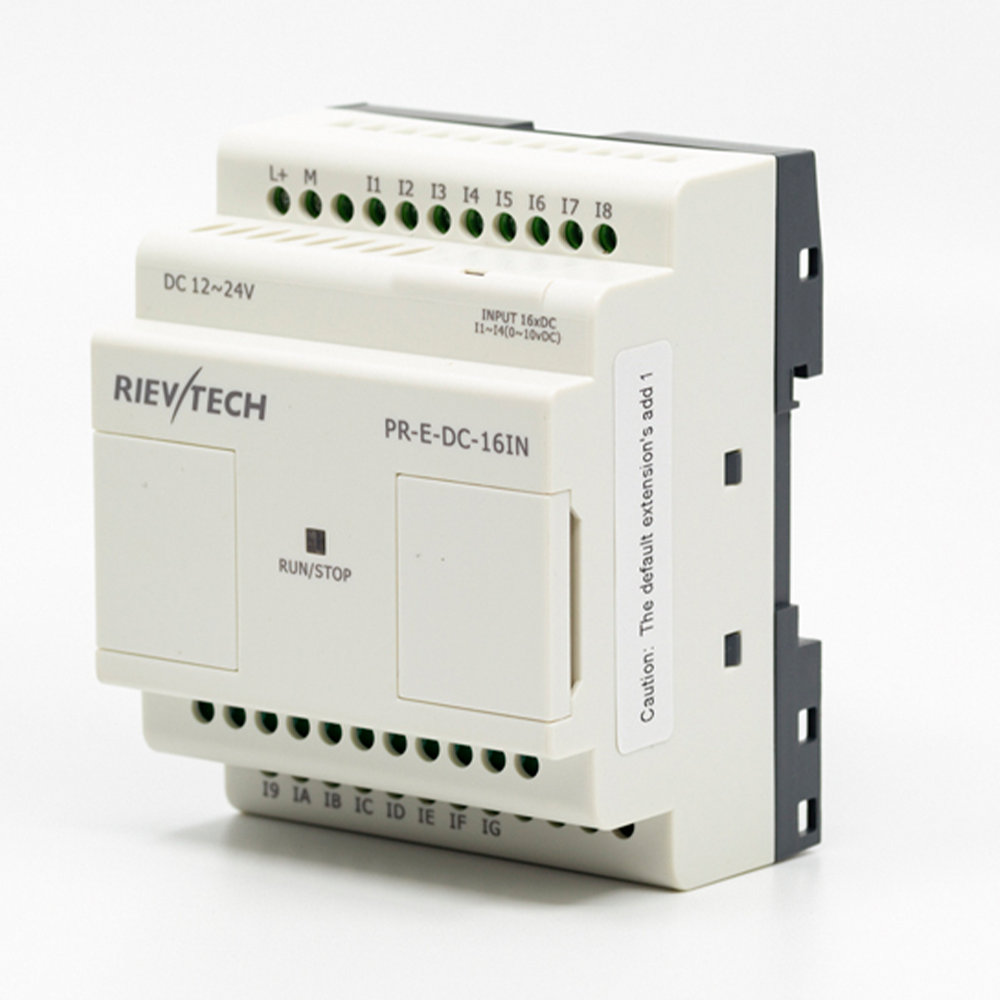
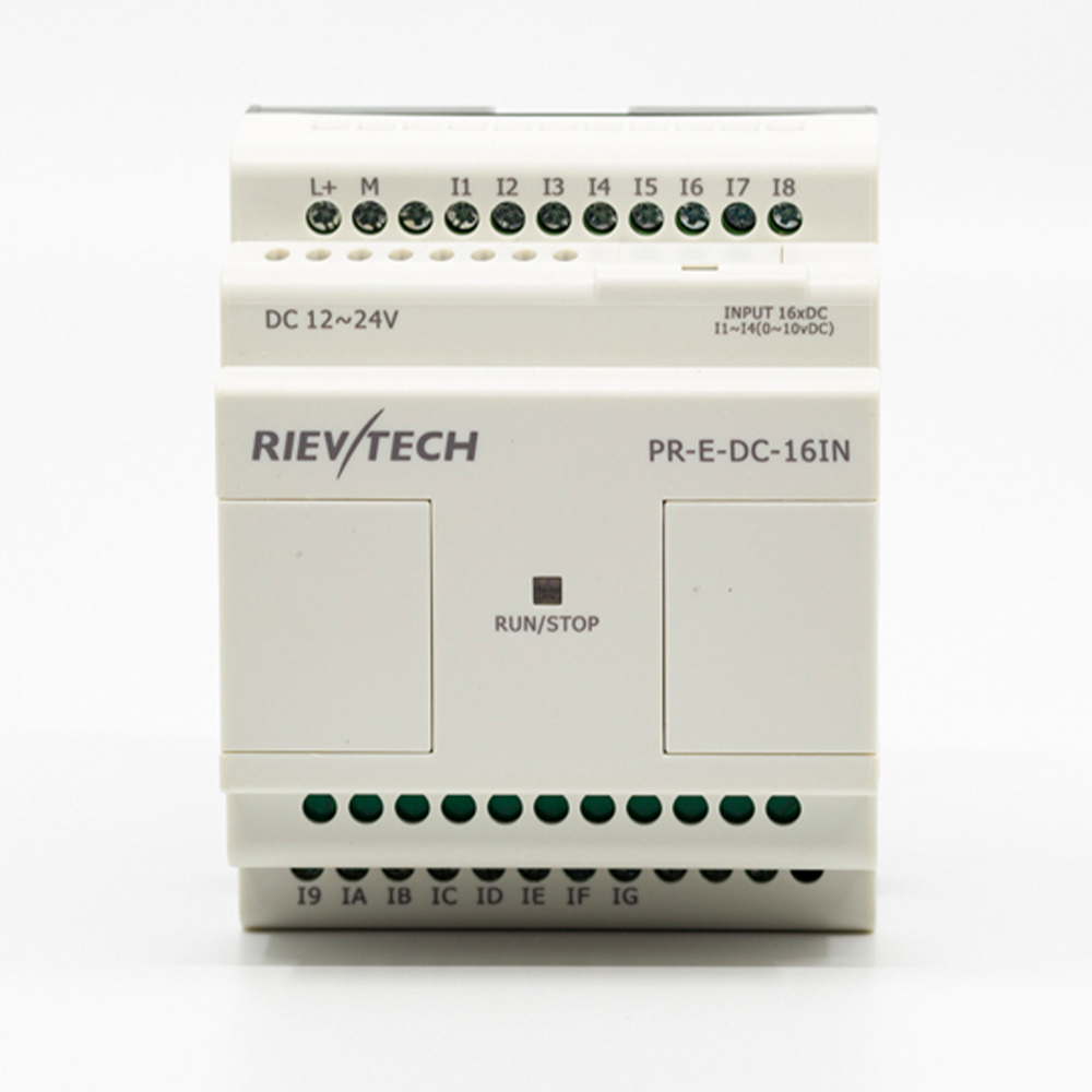
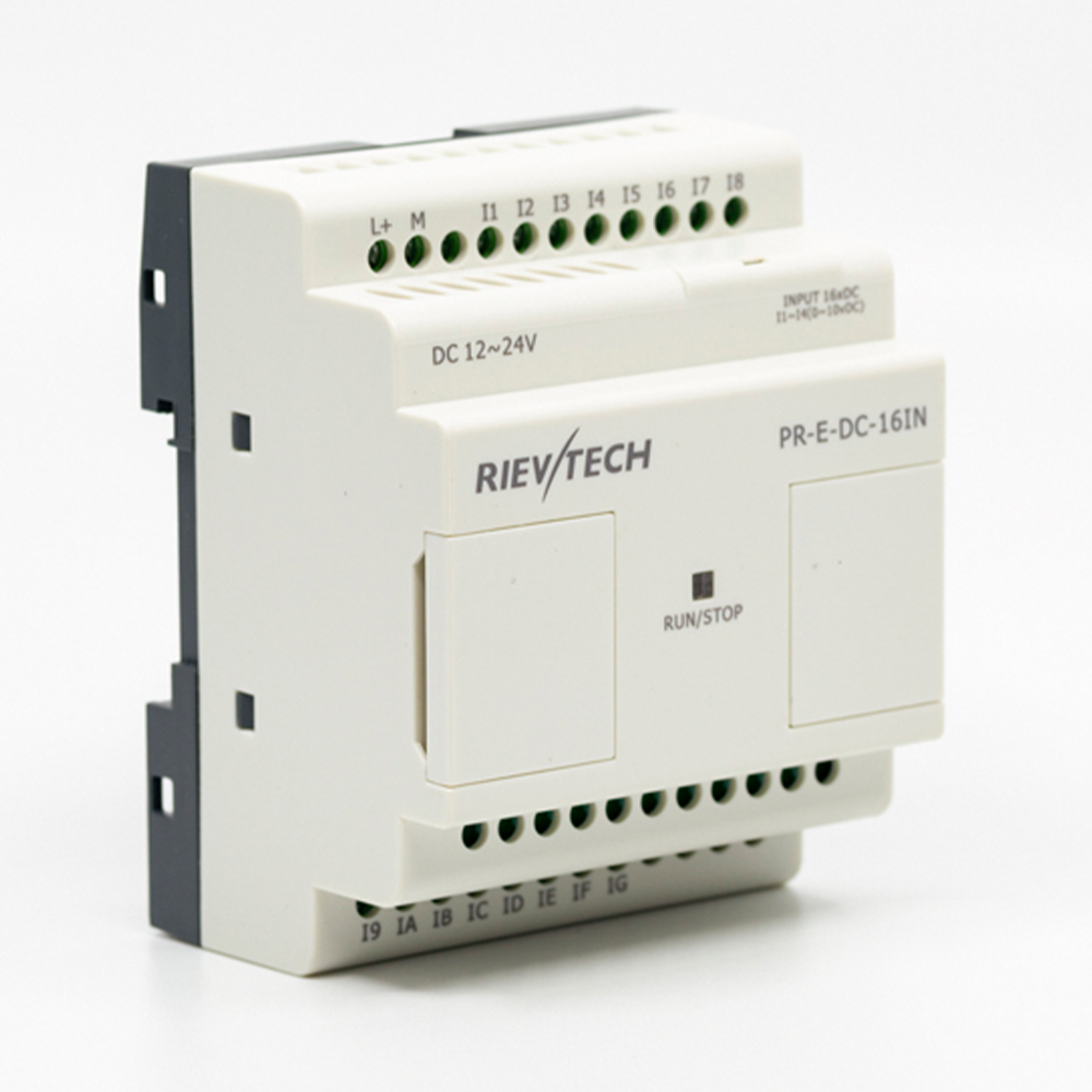
PR-E-DC-16IN is an expansion module adding 16 digital inputs (first 4 configurable as analog) to PR series CPUs — flexible input expansion for sensor-rich machines.
Specifications
|
Technical Index |
|
|
Power supply: |
|
|
Nominal voltage |
DC 12-24V |
|
Operating limits |
DC 10.8-28.8V |
|
Immunity from micro power cuts |
Typ.5 ms |
|
Max. Startup current |
Max. 0.4A |
|
Max. absorbed power |
0.7A (10.8V dc); 0.8 A (28.8V dc) |
|
Protection against polarity inversions |
Yes |
|
Input parameters: |
|
|
Input No |
16 (I1-IG) |
|
Digital input |
16 (I1-IG) |
|
Analogue input |
4 (I1-I4) (0...10V DC) |
|
Digital inputs( I5-IG ) |
|
|
Input voltage |
DC0-28.8V |
|
Input signal0 |
< 5V DC; <1mA |
|
Input signal1 |
> 8 V DC; >1.7mA |
|
Input current |
2.1 mA @ 10.8V dc
2.6 mA @ 12.0V dc 5.2 mA @ 24V dc 6.3 mA @ 28.8V dc |
|
Response time |
0 to 1 : <1 ms ; 1 to 0 : <1 ms |
|
Maximum counting frequency |
4 Hz(I5--IG) |
|
Sensor type |
Contact or 3-wire PNP |
|
Input type |
Resistive |
|
Isolation between power supply and inputs |
None |
|
Isolation between inputs |
None |
|
Inputs used as digital inputs (I1-I4) |
|
|
Input voltage |
DC0-28.8V |
|
Input signal0 |
< 5V DC;<0.09mA |
|
Input signal1 |
> 8 V DC;>0.15mA |
|
Input current |
0.4 mA @ 10.8V dc 0.5 mA @ 12.0 V dc 1.2 mA @ 24 V dc 1.5 mA @ 28.8 V dc |
|
Response time |
0 to 1 : <1 ms ; 1 to 0 : <1 ms |
|
Maximum counting frequency |
Typ.:4 HZ |
|
Sensor type |
Contact or 3-wire PNP |
|
Input type |
Resistive |
|
Isolation between power supply and inputs |
None |
|
Isolation between inputs |
None |
|
Inputs used as analog inputs (I1-I4) |
|
|
Measurement range |
DC 0---10V |
|
Input impedance |
Min, 24KΩ; Max. 72KΩ |
|
Input voltage |
28.8 V DC max |
|
Resolution |
9bit ,0.015V |
|
Accuracy at 25 °C |
± (Max.0.2)V |
|
Isolation between analog channel and power supply |
None |
|
Cable length |
10 m max. shielded and twisted |
|
Output parameters: |
|
|
Output No. |
None |
|
Other parameters: |
|
|
Operation temp |
-20℃-+55℃ |
|
Storage temp |
-40℃-+70℃ |
Address Setting for Expansion Modules
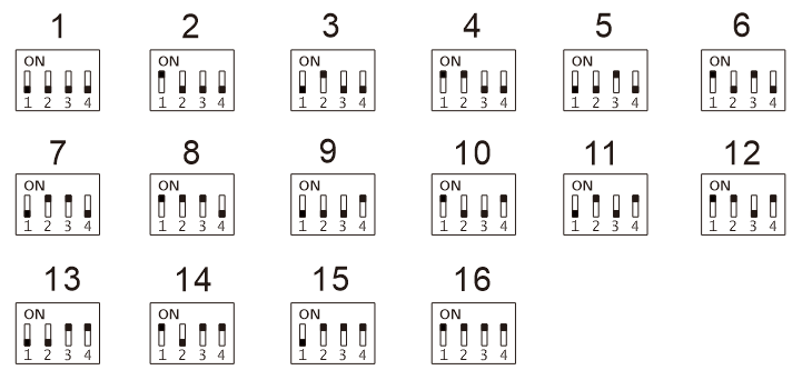
When multiple expansion modules are connected to one single CPU PLC, each expansion module must be assigned a distinct station address.
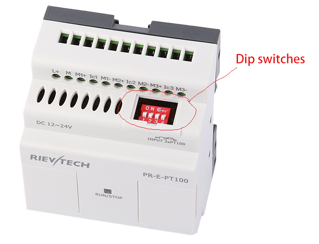
Factory default expansion address: 1. The expansion address is configured via DIP switch. The corresponding relationship between expansion address number and DIP switch status is shown below:
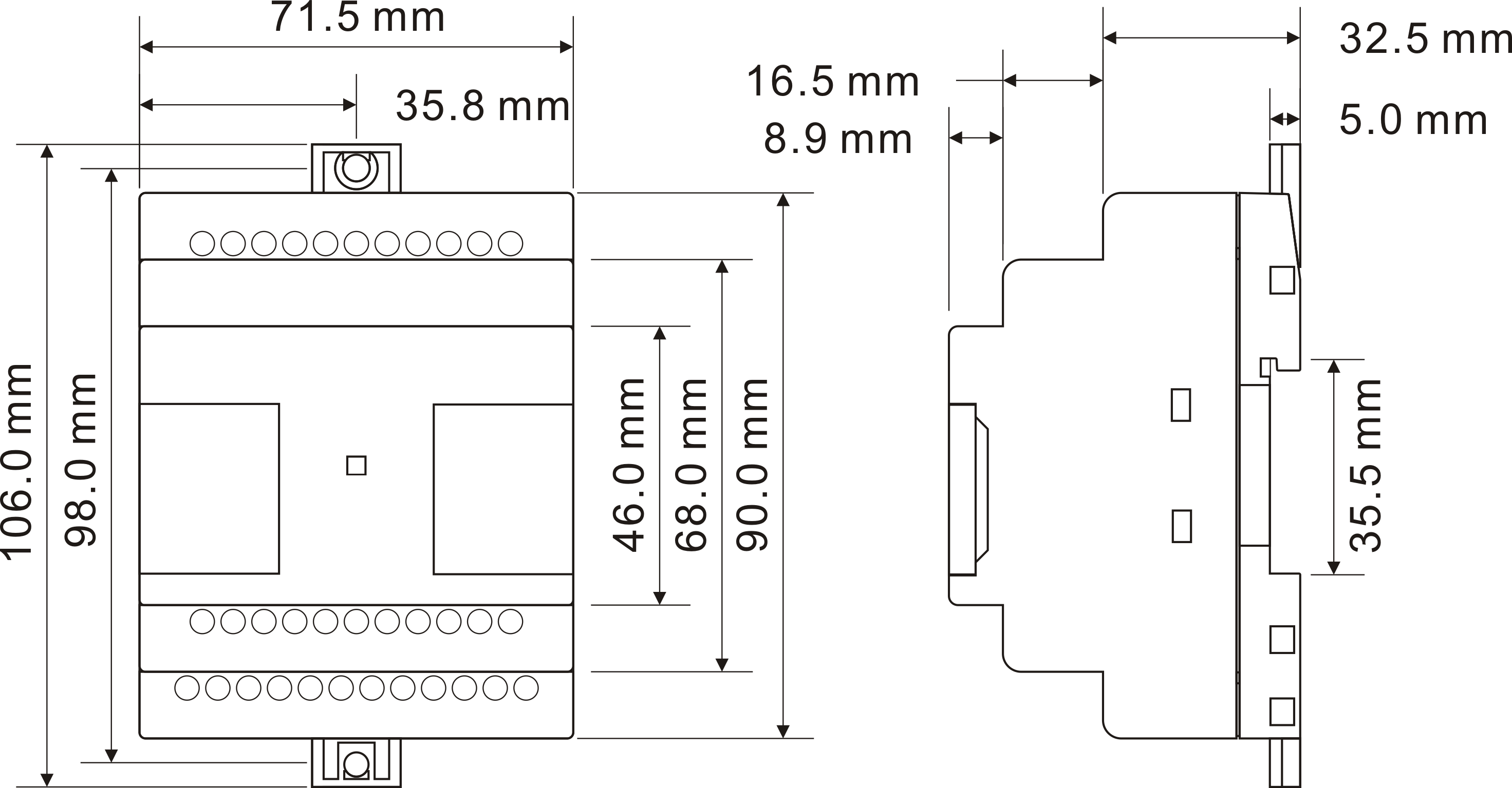
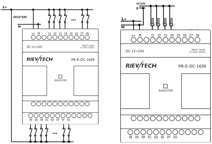
Installation Dimensions & Wiring Diagram