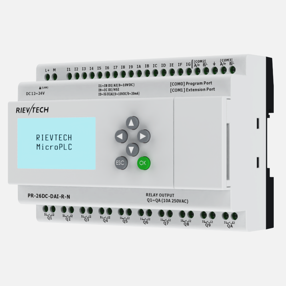
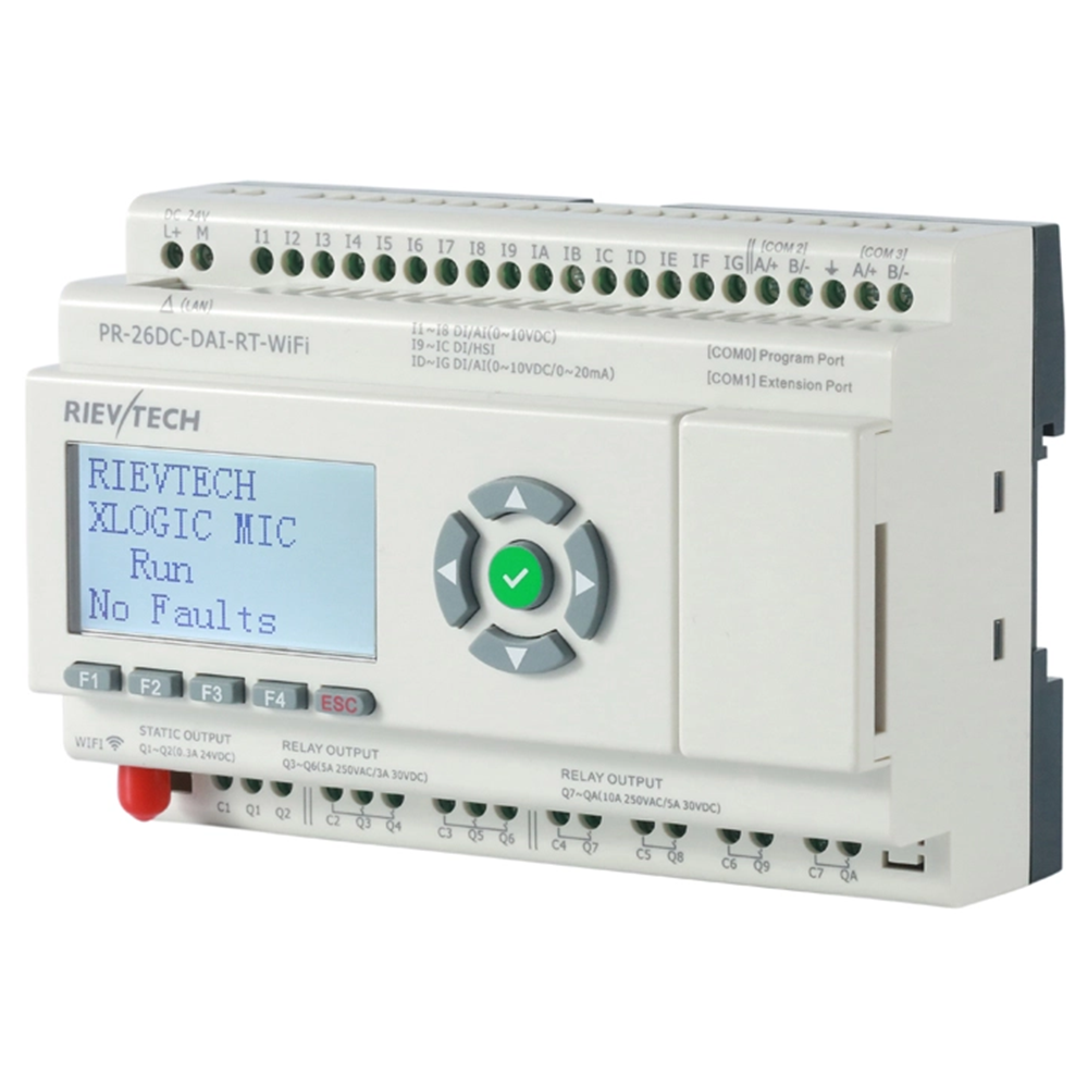
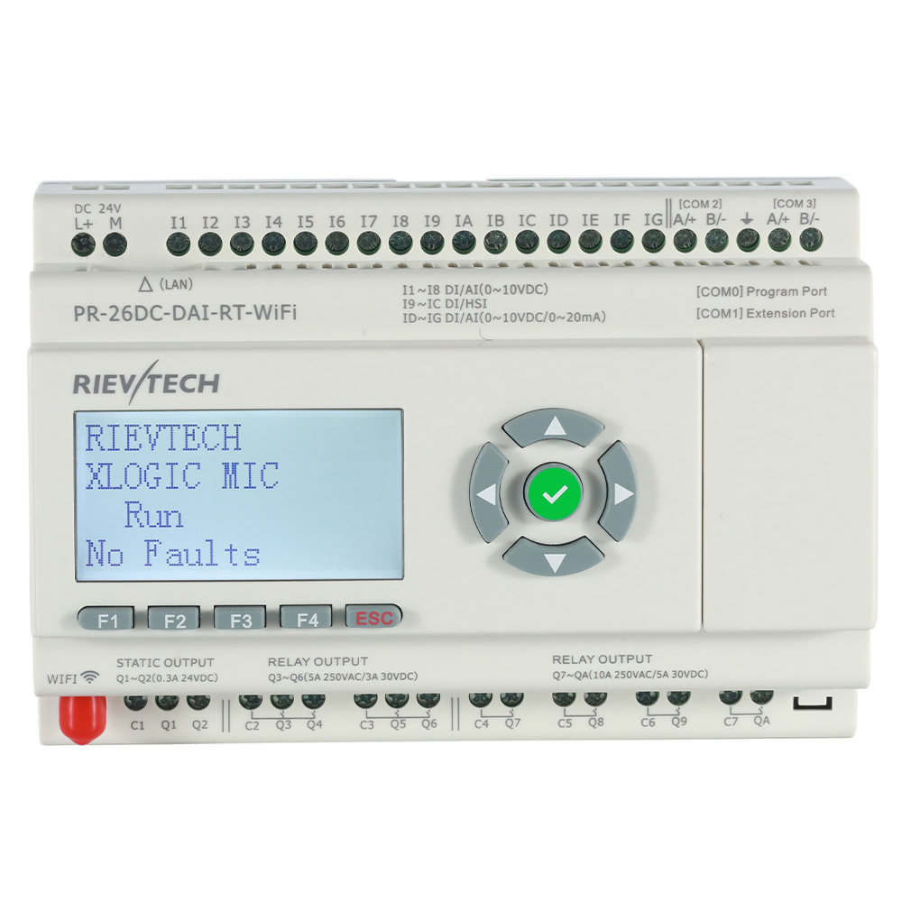
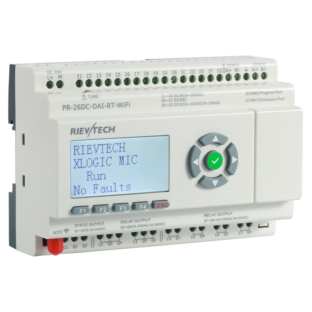
PR-26DC-DAI-RT-WIFI
Power supply: DC 24V
Input: 8 DI/AI(0-10V) + 4 DI + 4 DI/AI(0-10V/0-20mA)
Output: 2 Transistor (PNP) + 8 Relay
Ethernet, WiFi, 2 built-in RS485
Modbus RTU/ASCII, Modbus TCP, MQTT, BACnet MSTP / BACnet IP
PR-26DC-DAI-RT-WIFI is a 26-point WiFi PLC with mixed digital/analog inputs, transistor + relay outputs and Modbus, MQTT and BACnet over wired Ethernet plus WiFi access — retrofit networking without running new cables.
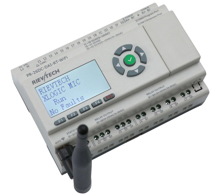
Specifications
Timers: 1024
Counters: 1024
Function Blocks: 1024
Operation temp.: -20°C - +55°C
Storage: -40°C - +70°C
Protection: IP20 (Non-waterproof)
RTC accuracy : MAX ±2S/day
RTC Backup at 25 °C: 20 days
Program and settings Backup: 10 years
Data Power-off retentivity: 10 years
Modify parameters via keypad LCD: YES
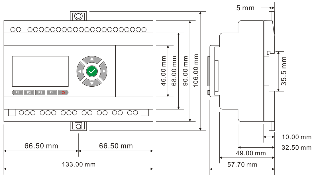
Dimensions: 133*90*60(Unit:mm)
Certificate: CE
Installation: 35-DIN rail or screw for installation
Supported programming language: FBD & Ladder
Expansion capacity: 16 modules (PR-E-16)
Password protection: 4-digit number password protection or disable program upload function
Communication interface: 1 RS232 Port (COM0 – RS232 Cable), 3 RS485 port (COM1 available via SR-RS485, C0M2&C0M3 - 2 built-in RS485 port), 1Ethernet port.
Communication protocol: Modbus RTU/ASCII, Modbus TCP
|
Technical Index |
|
|
Power supply: |
|
|
Nominal voltage |
DC 24V |
|
Operating limits |
DC 20.4-28.8V |
|
Immunity from micro power cuts |
Typ.5 ms |
|
Max. Startup current |
Max. 0.3A |
|
Max. absorbed power |
10W |
|
Protection against polarity inversions |
Yes |
|
Input parameters: |
|
|
Input No |
16 ( I1-IG) |
|
Digital input |
16 ( I1-IG) |
|
Analogue input |
8 ( I1-I8)(0...10V DC) +4(ID-IG)(0...20mA OR 0...10V DC) |
|
Digital input and analog inputs (0...10V)10bits ( I1-I8 ) |
|
|
Inputs used as digital inputs ( I1-I8 ) |
|
|
Input voltage |
DC0-28.8V |
|
Input signal0 |
< 5V DC;<0.08mA |
|
Input signal1 |
> 8 V DC;>0.12mA |
|
Input current |
0.16mA @ 10.8V dc 0.18mA @ 12.0 V dc 0.34mA @ 24 V dc 0.41mA @ 28.8 V dc |
|
Response time |
0 to 1 :Typ. 10.5 ms ;1 to 0 :Typ. 1.5 ms |
|
Maximum counting frequency |
Typ.:4 HZ |
|
Sensor type |
Contact or 3-wire PNP |
|
Input type |
Resistive |
|
Isolation between power supply and inputs |
None |
|
Isolation between inputs |
None |
|
Inputs used as analog inputs(0..10V) ( I1-I8 ) |
|
|
Measurement range |
DC 0---10V |
|
Input impedance |
Min, 24KΩ; Max. 72KΩ |
|
Input voltage |
28.8 V DC max |
|
Resolution |
10bit ,0.01V |
|
Accuracy at 25 °C |
± (Max.0.02)V |
|
Accuracy at 55 °C |
± (Max.0.04)V |
|
Isolation between analog channel and power supply |
None |
|
Cable length |
10 m max. shielded and twisted |
|
Digital and high speed inputs(I9--IC) |
|
|
Digital inputs ( I9-IC ) |
|
|
Input voltage |
DC0-28.8V |
|
Input signal0 |
< 5V DC; <1mA |
|
Input signal1 |
> 8 V DC;>1.6mA |
|
Input current |
2.1mA @ 10.8V dc 2.3mA @ 12.0 V dc 4.6 mA @ 24 V dc 5.5 mA @ 28.8 V dc |
|
Response time |
0 to 1 :<1 ms ;1 to 0 :<1 ms |
|
High speed inputs ( I9-IC ) |
|
|
Maximum counting frequency |
60kHZ(I9--IC) |
|
Digital and analog(0--10V)&analog(0...20mA) (ID-IG) |
|
|
Inputs used as digital inputs ( ID-IG ) |
|
|
Input voltage |
DC0-28.8V |
|
Input signal0 |
< 5V DC;<0.08mA |
|
Input signal1 |
> 8 V DC;>0.12mA |
|
Input current |
0.16mA @ 10.8V dc 0.18mA @ 12.0 V dc 0.34mA @ 24 V dc 0.41mA @ 28.8 V dc |
|
Response time |
0 to 1 :Typ. 10.5 ms ;1 to 0 :Typ. 1.5 ms |
|
Maximum counting frequency |
Typ.:4 HZ |
|
Sensor type |
Contact or 3-wire PNP |
|
Input type |
Resistive |
|
Isolation between power supply and inputs |
None |
|
Isolation between inputs |
None |
|
Inputs used as analog inputs(0..10V) ( ID-IG ) |
|
|
Measurement range |
DC 0---10V |
|
Input impedance |
Min, 24KΩ; Max. 72KΩ |
|
Input voltage |
28.8 V DC max |
|
Resolution |
10bit ,0.01V |
|
Accuracy at 25 °C |
± (Max.0.02)V |
|
Accuracy at 55 °C |
± (Max.0.04)V |
|
Isolation between analog channel and power supply |
None |
|
Cable length |
10 m max. shielded and twisted |
|
Input signal0 |
< 5V DC;<0.08mA |
|
Input signal1 |
> 8 V DC;>0.12mA |
|
Input current |
0.16mA @ 10.8V dc 0.18mA @ 12.0 V dc 0.34mA @ 24 V dc 0.41mA @ 28.8 V dc |
|
Response time |
0 to 1 :Typ. 10.5 ms ;1 to 0 :Typ. 1.5 ms |
|
Sensor type |
Contact or 3-wire PNP |
|
Input type |
Resistive |
|
Isolation between power supply and inputs |
None |
|
Isolation between inputs |
None |
|
Inputs used as analog inputs(0..20mA) ( ID-IG ) |
|
|
Analogue signal |
0/4….20mA current |
|
Input impedance |
260Ω |
|
Resolution |
0.02mA |
|
Accuracy at 25 °C |
0.05mA |
|
Cycle time for analog value generation |
Typ. 50 ms |
|
Protection against polarity inversions |
yes |
|
Overvoltage protection |
Yes, if the input voltage is >6.5V, this one is automatically switched on 0--10V configuration |
|
Isolation between power supply and inputs |
No |
|
Cable length |
<=30M with shielded twisted cable(sensor not isolated) |
|
|
|
|
Output |
|
|
Digital/Transistor output(PNP) - Q1,Q2 |
|
|
Breaking voltage |
DC 5--30V |
|
Nominal voltage |
≤ Supply voltage |
|
Nominal current |
Max. 0.3 A per channel |
|
Max. breaking current |
0.65 A |
|
Voltage drop |
< 2 V for I = 0.3 A (at state 1) |
|
Response time |
Make ≤ 1 ms Release ≤ 1 ms |
|
Frequency (Hz) |
resistive load : 10 Hz inductive load : 0.5 Hz |
|
Built-in protections |
Against overloads and short-circuits: No Against overvoltages (*): No |
|
Galvanic isolation |
None |
|
PWM frequency |
10K HZ |
|
PWM cyclic ratio |
0 to 100 % |
|
PWM accuracy at 120Hz |
< 0.5 % (20 % ➞ 80 %) load at 10 mA |
|
Max. Breaking current PWM |
50 mA |
|
Max. cable length PWM |
20m |
|
5A Relay 4 outputs from Q3 to Q6 |
|
|
Max. breaking voltage |
CE:AC 250 V/DC 30 V 5A UL:AC 250 V/DC 30 V 3A |
|
Electrical durability Expectancy |
10 5 Operations at Rated Resistive Load |
|
Mechanical life |
10 7 Operations at No Load condition |
|
Response time |
Operate Time: 15 mSec. Max. Release Time: 10 mSec. Max. |
|
Built-in protections |
Against short-circuits: None Against overvoltages and overloads: None |
|
10A Relay 4 outputs from Q7 to QA |
|
|
Max. breaking voltage |
CE:AC 250 V/DC 30 V 10A UL:AC 250 V/DC 28 V 5A |
|
Max. Allowable Power Force |
1250VA |
|
Electrical durability Expectancy |
10 5 Operations at Rated Resistive Load |
|
Mechanical life |
10 7 Operations at No Load condition |
|
Response time |
Operate Time: 15 mSec. Max. Release Time: 10 mSec. Max. |
|
Built-in protections |
Against short-circuits: None Against overvoltages and overloads: None |
|
Communication ports parameters: |
|
|
COM0_TTL port |
Can be used as program port with PR-RS232&PR-USB; Also can be convert to RS232 port with PR-RS232 Can be convert to RS485 port with PRO-RS485 Note:Need move away the expand cover to use it Can be used as modbus master or slave |
|
Built-in RS485 COM2 |
1 built-in RS485 port (Terminal A+,B-) Can be used as modbus master or slave |
|
Built-in RS485 COM3 |
1 built-in RS485 port (Terminal A+,B-) Can be used as modbus master or slave |
|
Ext RS485 COM1 |
Need use with PR-E-RS485 module Can be used as modbus master or slave |
|
Ethernet port: |
Built-In(10M/100M), 1.Can be used as program or communication 2.Can be used as modbus master or slave |
|
Monitoring webserver page |
Yes |
|
Xlogic<--->Xlogic(by Ethernet) |
1 xlogic works as tcp server can connect with 8 tcp client xlogics or other tcp devices. |
|
Xlogic<--->Ethernet/Internet: |
1 xlogic works as TCP clients can connect with 8 different tcp servers separately in maximum |
|
|
|
|
Other parameter |
|
|
Weight |
Approx.400g |
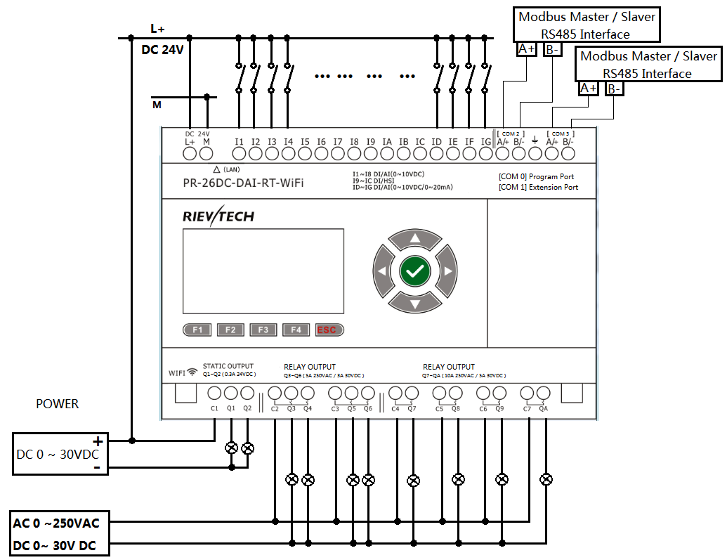
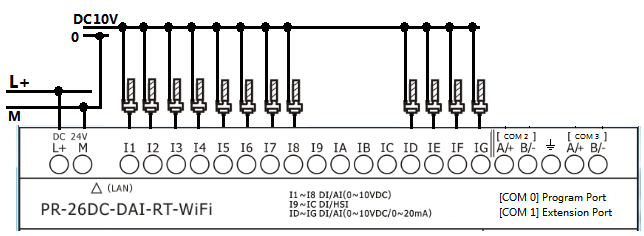
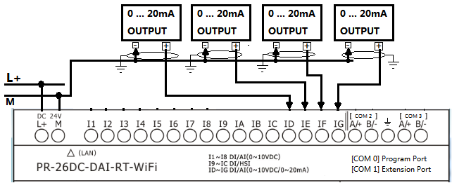
Installation Dimensions & Wiring Diagram